Moog | Installation instructions series G400
English
09/2008
Introduction
Brushless construction means that MOOG G400 series
servodrives are maintenance free. The longevity of the
motors is limited only by the life of the bearings, which
have a lifetime lubrication (a minimum of 20,000 opera-
tion hours with the recommended maximum axial and
radial loads). Because of product liability issues any
motor damage should be repaired by MOOG, non MOOG
staff may be unable to comply with safety rules (e.g. VDE
guidelines) and MOOG quality standards.
Caution: Destruction of the paint seal on the screws
voids warranty.
Recommended drives to be used to control the motor,
according to UL1004, Par.30.6: MSD Series, DS2000 by
Moog.
Shipment
Please check the contents of delivery are as ordered
and that no damage, especially the areas of the shaft
and connectors, has occurred during transit. Any prob-
lems should be immediately addressed to MOOG with a
description of the fault or damage.
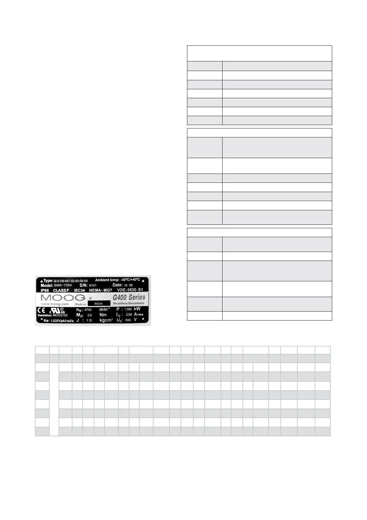
G400 series motor codication
The motor nameplate data are used for the setting of the
servodrive. In case of contact with Moog, identication
data of the motor must be supplied.
Example:
Technical data
data are measured at 25°C ambient temperature
n
N
nominal speed at PN
P
N
nominal power (max continuous output power)
M
0
continuous stall torque
I
0
continuous stall current (at M
0
)
K
e
back emf (voltage constant)
J
rotor moment of inertia
U
d
nominal operatine voltage (bus voltage)
Nameplate data
Type
motor type
(Note: for motors built before July 2008 this
may vary)
Ambient
temp
ambient temperature
Model
motor model number (ordering number)
S/N
serial number
Date
week and year of production
Insulation
UL approved insulation system
Brake
Brake is optional. Data provided refers to
holding torque
Standards
IP65
degree of protection. Motor protected against
jets of water (at shaft with seal option)
I.CL.F
motor listed for insulation class F (155°C)
IEC34
motor fullls IEC34 (Standard denes rating
and performance of rotating electrical ma-
chines)
VDE-0530-
S1
performance measurements are done according
to VDE-0530
CE
conformity certicate will be supplied on
request
UL
motor c-UL Recognized, le number E137630
Installation instructions
General
Standards
Technical
data
Mounting dimensions for MOOG motors
Type A Pmax C øAJ øAK AH øU BB
max
øBF XD R S1xS2 D BC øE F G H M
mm mm mm mm mm mm mm mm mm mm mm mm mm mm mm Nm
G-1
See tables at page 13
40 7.0 48 18
+0.008
-0.003
16 6
+0.006
-0.002
2.5 3.3 10 4.8 2x2 1.5 0 14
+0.027
-0.000
- M2.5x8 M3x16 1.3
G-2
55 9.0 63 40
+0.011
-0.005
20 9
+0.010
+0.001
2.5 5.5 14 7.2 3x3 3 0 24
+0.003
-0.000
- M2.5x8 M5x22 5
G-3
70 9.0 75 60
+0.012
-0.007
23 11
+0.012
+0.001
2.5 5.5 16 8.5 4x4 4 0 24
+0.003
-0.000
- M2.5x8 M5x22 5
G-4
100 9.8 115 95
+0.013
-0.009
40 19
+0.015
+0.002
3 9 32 15.5 6x6 4 0 35
+0.039
-0.000
66.3 M4x16 M8x30 16
G-5
140 12.2 165 130
+0.014
-0.011
50 24
+0.015
+0.002
3.5 11 40 20 8x7 5 0 47
+0.039
-0.000
98.8 M4x16 M10x40 30
G-6
190 11.0 215 180
+0.014
-0.011
60 32
+0.018
+0.002
4 13.5 40 27 10x8 10 0 50
+0.039
-0.000
128 M4x16 M12x40 38
ISO
286 286 286 286 286 286 286 286 286 286 286
DIN
6885 6885 13-1 912 8.8 912 8.8
A Length of mot or without shaft, pilot and mating connector
Pmax Maximum width of motor (end view) excluding terminal housing, etc.
C Thickness of ange plate of motor
øAJ Diameter of mounting bolt circle in ange of motor
øAK Diameter of pilot on ange of motor AH Mounting surface of ange of
motor to end of shaft
øU Diameter of shaft extension
BB
max
Maximum height of pilot of mounting ange of motor
øBF Clearance hole in mounting ange of motor
XD Usable length of keyseat
R Bottom of keyseat to opposite side of shaft
S1 Width of key
S2 Height of key
D Distance between end of shaft and key
BC Distance between mounting ange of motor to shoulder shaft
(always=0mm)
øE Diameter of hole for shaft in ange of motor
F Width of motor between recesses for mounting screws
G Thread in motor shaft
H Recommended ange screws (kind and length)
M Tightening torque for ange screws
All dimensions without tolerance are according to DIN ISO 2768, part 1, category c.
2

 Loading...


