Operator’s Manual, Morbark Integrated Control System—Model 20 Chipper
7
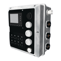
Parts Identification
Panel / Valve Driver Parts Identication
No. Description
1
Master Display Module
2
Manual Controls / Keypad
Feed Forward — Engage the Feed System•
Feed Reverse — Reverse the Feed System•
Yoke Up — Raise the Yoke•
Yoke Down — Lower the Yoke•
Spout Left — Rotate the Spout Left•
Spout Right — Rotate the Spout Right•
Throttle Increase — Increase the speed of the Engine•
Throttle Decrease —Decrease the speed of the Engine•
3
Diagnostics Connector
4
Tether — Connection Point for the Tether control
5
Cat Data Link
6
John Deere or Cummins Data Link
7
Key Switch
8
Modem Option Connector
9
Battery connector — To “Main Disconnect” and Negative (-) post on Starter
10
Engine Connector — Connects to the Engine on the Machine
11
Input Harness Connector
Hood Switch•
Feed Stop•
Feed Bar Proximity Switch•
Fuel Gauge•
12
Output Harness connector
Feed Forward•
Feed Reverse•
Yoke Up•
Yoke Down•
Right Track Forward•
Right Track Reverse•
Left Track Forward•
Left Track Reverse•
Spout Left•
Spout Right•
Winch In•
Winch Out•
Track Drive High•
Track Drive Enable•
Fan Reverse•