Description Nm lb‑in. lb‑ft
Cable tension screw 1.7 15 –
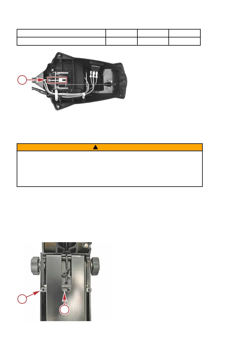
Bottom of foot pedal
a - Cable tension screw
Front Locking Pin Replacement
The front locking pin can be easily replaced if the locking pin is damaged. Refer
to the following instructions and follow them completely for a successful repair.
!
WARNING
Performing service or maintenance without first disconnecting the battery can
cause product damage, personal injury, or death due to fire, explosion,
electrical shock, or unexpected motor starting. Always disconnect the battery
cables from the battery before maintaining, servicing, installing, or removing
motor components.
1. Pull the latch release handle and open the mount to a position where it is
part way between the stowed and deployed positions. Support the mount
in this position.
2. Pull and hold the latch release handle until the lock is aligned as shown.
Hold the latch release handle in this position.
IMPORTANT: Do not release the latch release handle until the new locking pin
is installed, or internal damage to the mount will occur.
a - Locking pin
b - Lock
MAINTENANCE
34 eng
 Loading...