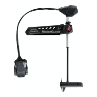
3. Once the lock is aligned as shown, press the locking pin in the direction
indicated, but do not remove it completely.
NOTE: If required, tap the locking pin out with a screwdriver handle or small
hammer to disengage the locking pin.
4. Continue to hold the latch release handle once the locking pin is partially
removed.
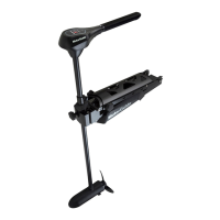
5. Orient the new locking pin so the alignment tab is facing the same
direction as the alignment tab of the old locking pin.
6. Press the new locking pin into the opposite side of the mount. Continue to
press the new locking pin until it clicks into position.
NOTE: The new locking pin will press out the old locking pin as it is installed.
a - Alignment tabs
7. Release the latch release handle and move the trolling motor to the
stowed or deployed position as desired.
MotorGuide Accessories Inquiries
Refer to www.motorguide.com for factory authorized accessories for all
MotorGuide trolling motors.
MAINTENANCE
eng 35
 Loading...