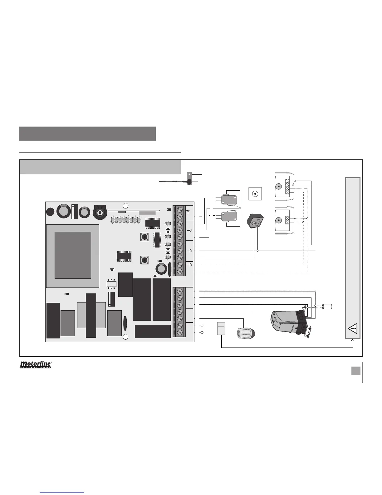
. THE CONTROL BOARD
CONNECTION SCHEME
L LAMP MOTORE
ANTENNA
PUL DS
FAP FCH
AP COM CH
N
230~
CN1
CN2
230~
24V
SEL SET
VR1
CODE
CODE PED
IN.CMD.AP.
LAMP/CORT
PGM.AUT
T.MOT
T.MOT.PED
T.PAUSA
F1
F2
DV NCCOM
12/24V
DV
12/24V
~~~~
(or)
OPEN
PHASE
NEUTRAL
FLASHLIGHT
MOTOR
CAPACITOR
LIMIT-SWITCHES
KEY SELECTOR / PUSH BUTTON
ANTENNA
PHOTOCELLS
110V
or
230V
CLOSE
1 13 35 52 24 46 67 7 8 9 10
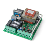
The MC1 is an electronic single phase control board with control system via built-in
radio, developed for the automations control for sliding gates or just 1 motor for swing
gate.
TRANSFORMER
110V OR 230V
ATTENTION:
The control board power supply depends on the value described in the
transformer!