. THE CONTROL BOARD . THE CONTROL BOARD
TECHNICAL SPECIFICATIONS
FCH
PUL
This LED signals the connection of accessories which control automatism
functioning like key selectors or push buttons. It lights up when it receives
accessories signals (contact changes from NO to NC). If you need to connect
several components in this entry, they must be connected in parallel mode
(direct connection on connector).
DS
The LED signals the connection of safety devices such as photocells or safety
edge (required to MR12 connection). This LED is lit when a device is connected
at the DS input (NC). Whenever the contact safety device is interrupted (NO |
eg object between photocells), the LED turns off.
If you need to connect multiple components on this input, they must be
connected in series mode.
FAP
LED signals the connection of the opening limit switch. This LED stays lit as
soon as the opening limit switch is connected into the terminal 6 of CN2 (NC).
Whenever the opening limit switch is activated (NO), the LED will turn off.
FCH
LED signals the connection of the closing limit switch. This LED stays lit as
soon as the closing limit switch is connected into the terminal 6 of CN2 (NC).
Whenever the closing limit switch is activated (NO), the LED will turn off.
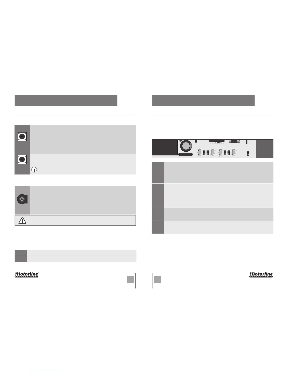
• LEDS
There are LEDs in the control board to inform the installer about connection status of
the various components. Before the central configuration, note the behavior of these
LEDs, which must match those described in the table below.
• SEL/SET BUTTONS
• MOTOR'S FORCE AND SPEED
TECHNICAL SPECIFICATIONS
SEL key:
To select the function to change. This selection is identified by the
intermittency of LED corresponding to the selected function at that time.
Pressing the SEL key repeatedly will cycle through the various functions
to be programmed. The selection remains active for 10 seconds, and
after that time the control board returns to the original state (no active
selection).
SET key:
To program the selected function with the SEL key.
SEL
SET
The SET key can be replaced by transmitter key, as long it finds itself
programmed.
VR1 potentiometer:
The control board has a "VR1" potentiometer to adjust the force and
speed of the motors, controlled by the microprocessor. Adjustment can be
made between 50% and 100% force / speed.
In each starting movement, the control board applies the maximum force
for 2 seconds, even when a force adjustment is made to a value other
than the maximum.
VR1
When you adjust the VR1 potentiometer, it is necessary to redo the programming
course, because the maneuver and slowdown times may vary.
• FUSES
There are two fuses that protect the center against electrical overloads. These protection
devices are an essential part of the power distribution system as they prevent damage
to other circuit elements.
F1
T6.3AL250V - 3A 250V
F2
50mAL250V - 50mA 250V