After installing the control board and connecting the wires, you must ensure that all
connected components are working properly. To do this, follow these steps:
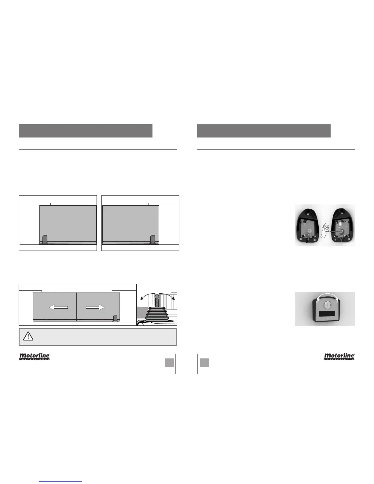
First, you must define whether the operator is installed on the right or left of the gate.
This information will indicate which side is the opening and closing.
The photocells are a safety device that inform the control board that an object is
obstructing the gate's route. They send a signal to prevent the gate from damaging the
object.
The photocells are connected to the control board DS input (see wire connection
page). This input has an assigned LED that informs about the connection status of the
Components as key selector or push buttons are used to control the functioning of
the gate. These components are connected to the control board PUL input (see wiring
diagram on page 2). This input has an LED assigned that informs the connection status
of the connected components. This LED remains off when a component is connected
(NO mode).
To test the connection of photocells in the control
board, just interrupt the signal between the two
photocells putting his hand in front of one of them.
A sound similar to a "click" indicates that the signal
was interrupted and the LED DS should be off while
the photocells are interrupted. If it does not operate
on this way, there is a problem in the connection
between the photocells and the control board.
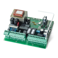
To test the key selector connection in the control
board, simply turn the key to one of the directions.
At this time, the PUL LED lights up (NC), and turns off
when the key go back to the original position (NO). If
it does not operate on this way, there is a problem in
the connection between the device and the control
board.
This test will be exemplified with the automation installed on the right.
Lean the automatism limit switch spring to the right until you hear a "click". The FAP LED
must turn off! Now Lean the automatism limit switch spring to the left until you hear a
"click". The FCH LED must turn off!
If the LEDs turn off oppositely, reverse the wires to the terminals 6 and 8 of CN2.
• LIMIT SWITCHES TEST
• PHOTOCELLS TEST
• KEY SELECTOR TEST
LEFT
INSTALLATION
RIGHT
INSTALLATION
. PROGRAMMING . PROGRAMMING
PREINSTALLATION WARNINGS PREINSTALLATION WARNINGS
The limit switches are an important safety system of the motor. It is extremely
important that they are properly connected in the control board, otherwise it
may cause serious damage or injury.
OpenClose