8-20 Disassembly/Reassembly Procedures: Radio Reassembly
8.6 Radio Reassembly
This section contains instructions for reassembling the radio.
8.6.1 Reassemble the Main Board (33)
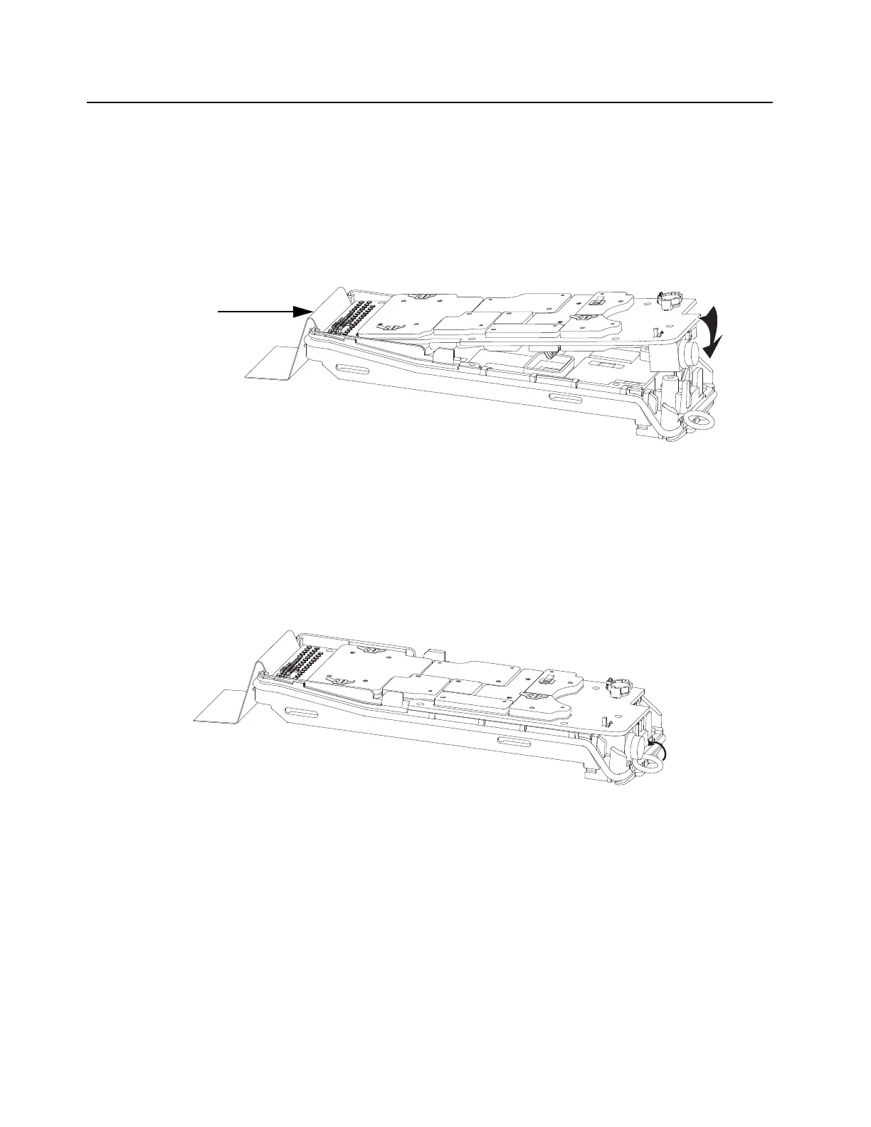
1. Plug in the connectors of the Back Kit Flex (31) onto the Main Board (33). With the Back Kit
Flex connected to the Main Board, place the Main Board into the Chassis (41) as shown in
Figure 8-26.
.
Figure 8-26. Assemble the RF Board
NOTE: Plug in the connectors at the side of the Back Kit Flex which reads “To Main Board”. Ensure
that the Battery Contact Seal (42) does not pinch and the tabs of the Main O-Ring are held in
place when assembling the Main Board into the Chassis.
2. With the Main Board (33) seated in the Chassis (41), gently assemble the Main O-Ring (36)
to the Antenna Holder as shown in Figure 8-28.
.
Figure 8-27. Assemble the Main O-Ring at Antenna Holder

 Loading...


