6-16 Radio Alignment Procedures: Transmitter Alignments
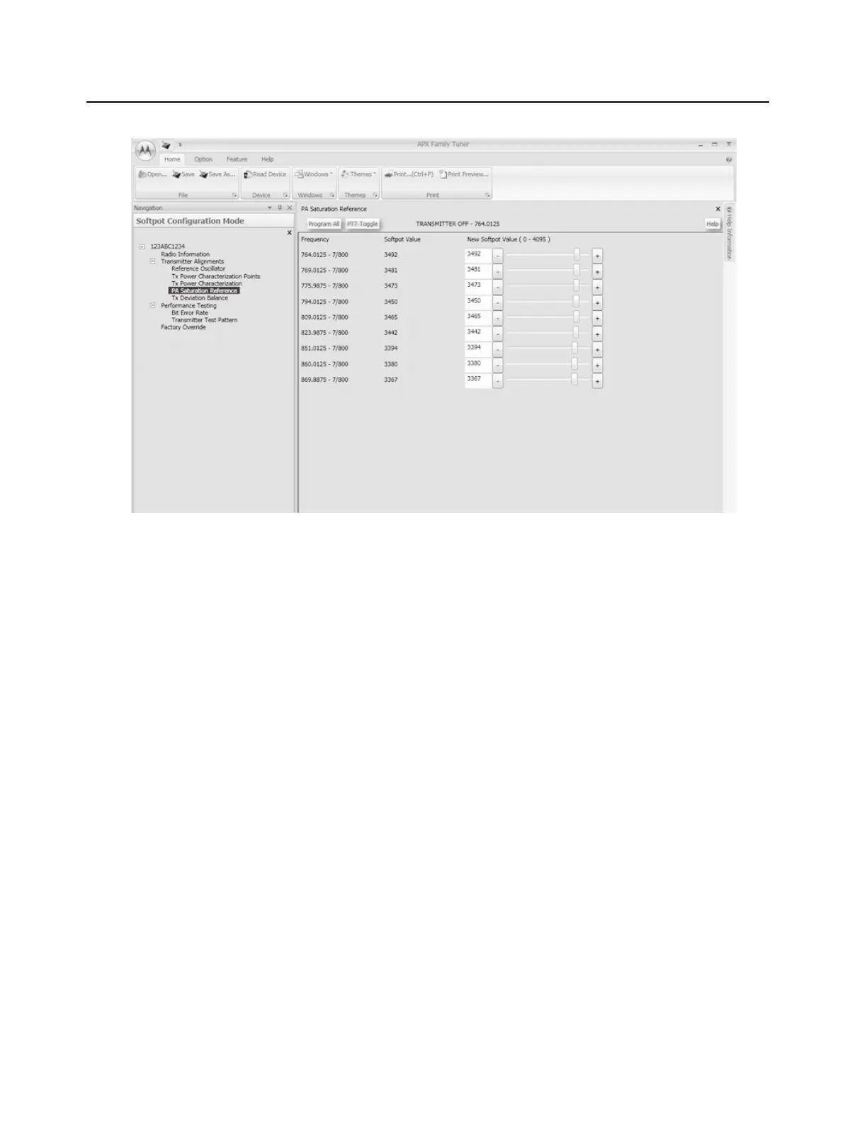
Figure 6-20. PA Saturation Referencing Alignment Screen (700/800 MHz)
6.5.5 Transmit Deviation Balance Alignment
This alignment procedure balances the modulation contributions of the low- and high-frequency
portions of a baseband signal. Proper alignment is critical to the operation of signalling schemes that
have very low frequency components (for example, DPL) and could result in distorted waveforms if
improperly adjusted.
This procedure needs to be performed at multiple frequencies to allow for proper alignment across
the entire RF band. The RF band is divided into frequency zones with a calibration point (value) in
each zone.
NOTE: This alignment is required after replacing (or servicing) the main board.
Proper alignment requires a modulation analyzer or meter with a frequency response to less than
10 Hz modulating frequency. The modulation analyzer settings during this test should be set for
average deviation, a 15 kHz low-pass filter, no de-emphasis, and no high-pass filter, if these settings
are supported.
This alignment can be done with either the R-2670 Communication Analyzer or the 8901_ Series
Modulation Analyzer. The method of choice is the R-2670 analyzer.
1. Initial setup using the R-2670 Communication Analyzer:
- Connect a BNC cable between the “DEMOD OUT” port and the “VERT/SINAD DIST/DMM
COUNTER IN” port on the R-2670.
-Press the SPF key on the R-2670 to display the “SPECIAL FUNCTIONS MENU.” Move the
cursor to “High Pass,” and select 5 Hz on the soft key menu. Select 20 kHz for the “Low
Pass” setting.

 Loading...


