Troubleshooting Charts 5-21
6881076C25-D October 28, 2002
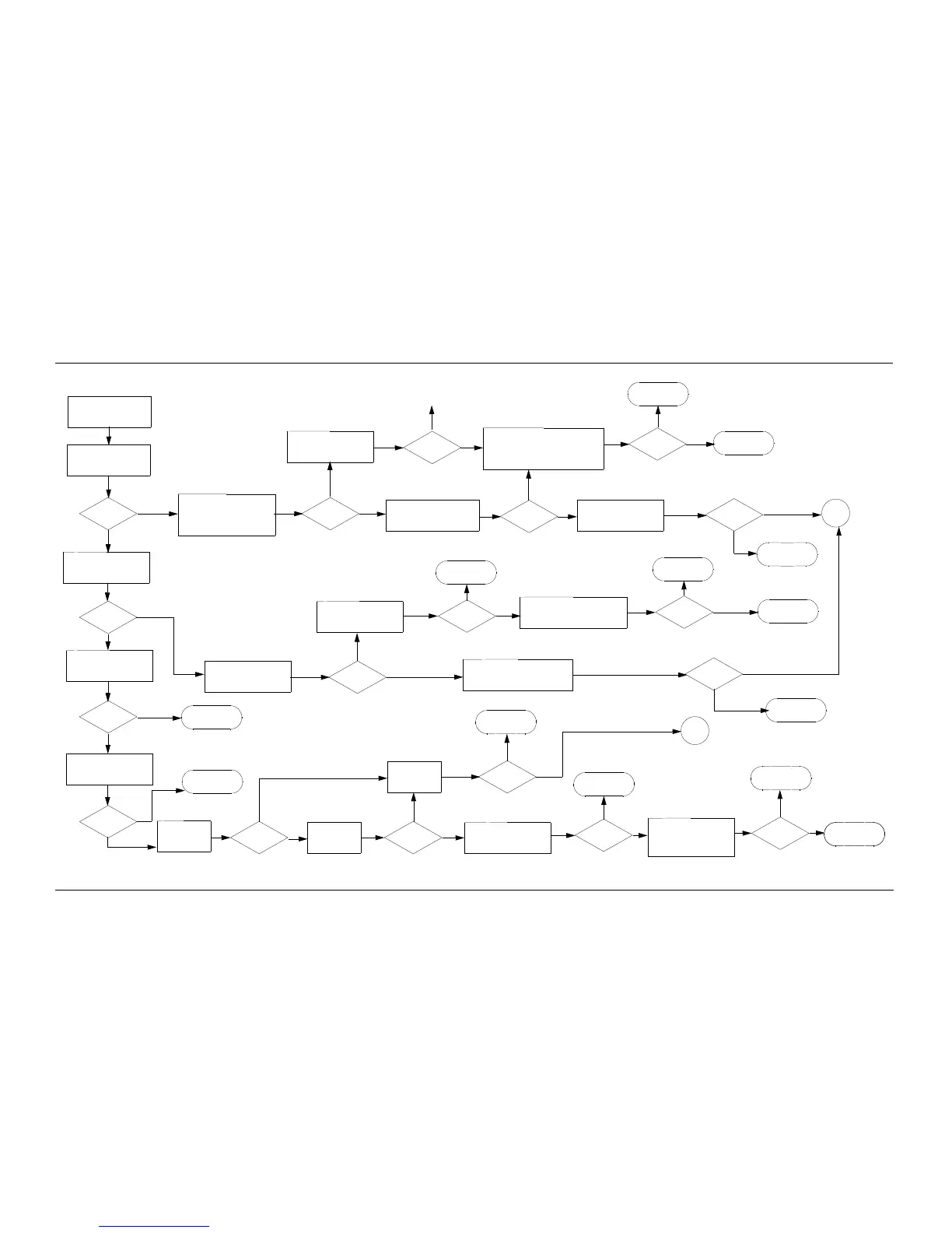
Chart C.27 ASTRO Spectra Plus VOCON TX Modulation Failure Sheet 1 of 4
No
Yes
A
B
Yes
No
Inject a 1kHz tone into MIC
with sufficient amplitude to
produce 3kHz of deviation,
PTT radio
Measure waveform at
TP208, should match
Figure 6-13
Waveform
Correct?
Amplitude of
Waveform
may vary
Measure waveform at R208
(left) should match Figure 6-13
Waveform
Correct?
Check 5V supply of U202-8
and GND U202-4
Measure waveform at
TP209, should match
Figure 6-13
Waveform
Correct?
Amplitude of
Waveform
may vary
Amplitude of
Waveform
may vary
OK?
Inspect and Repair
U202
Measure waveform at
should match Figure 6-13
U201-9
Make sure the following components
are placed and soldered correctly:
U202, R207, R208, C216, R209, R226,
C223, C217
OK?
Repair proper
components
Replace U202
No
Yes
No
Yes
No
Yes
No
No
Yes
Waveform
Correct?
No
Yes
Check that 3V is present at
U201-45, 31, 27, 3. Check
GND at U201-30, 28, 4
OK?
Measure waveform at J501-49
should match Figure 6-13
Amplitude of
Waveform
may vary
Waveform
Correct?
Inspect and repair
J501
Yes
Yes
No
No
Measure waveform at J501-48
should match Figure 6-13
Amplitude of
Waveform
may vary
Waveform
Correct?
Inspect and repair
J501
No
Yes
Keyed 9.4V
Check for 5V at
J501-45
Present?
Yes
No
Check for GND
at J501-14
Inspect J501
connections
Present?
No
Yes
OK?
Make sure the following parts
are the correct value: R207,
R208, R209, R226, R202,
R231, C216, C215
Correct?
Replace proper
components
Yes
No
No
Repair J501
Yes
Make sure the following parts
are the correct value: R401,
R408, R405, C405, C403,
R400, R407, C402, R438,
R437, R406, C404
Correct?
Yes
No
No trouble
found
Replace proper
components
Measure waveform at C203
and C204, should match
Figure 6-14 Traces 1 and 2
Waveform
Correct?
Check 5V supply of U202-8
and GND U202-4
Make sure the following components
are placed and soldered correctly:
U202, R202, R231, and C215
Check that 3V is present at
U201-45, 31, 27, 3. Check GND
at U201-30, 28, 4
OK?
Repair U201
Yes
OK?
Yes
No
Inspect and repair
U202
Repair U201
Replace U202
Repair proper
components
OK?
Yes
No
Amplitude of
Waveform
may vary
Continued on
next page
Continued on
next page

 Loading...


