_)
2-1
Chapter 2
Theory
of
Operation
2.1
Overview
This chapter provides a detailed theory
of
operation for the radio and its components. The radio is
designed as a single board unit consisting
of
a transmitter, receiver, and controller circuits. The
board also accepts one additional option board that can provide functions such as secure voice/
data, voice storage, or a
signalling decoder.
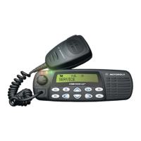
A control head, mounted directly on the front
of
the radio or remotely connected by an extension
cable, provides a user interface for
controlling the various features
of
the
radio. The control head
contains LED indicators, microphone connector, and buttons depending on the radio type, display,
and speaker.
The rear
of
the radio provides connections for a power, antenna, and accessory cable. The
accessory cable provides connections for items such as an external speaker, emergency switch,
foot operated
PTT,
and ignition sensing, etc.
2.2 Controller
The radio controller, shown in Figure 2-1,
is
divided into three main functions:
Digital control
Audio processing
Voltage regulation.
The digital control section
of
the radio consists
of
a microprocessor (IJP), support memory, support
logic, signal MUX
ICs, on/off circuit, and general purpose input/output circuits.
To
Synthesizer
16.8 MHz
Reference
Clock
from Synthesizer
5V
from Synthesizer
Mod
Out
r----
---
-------,
Audio/Signalling
ASFIC_CMP
External
Microphone
External
Speaker
Section (5V_RF)
-or----__;;,
____
.J
Internal
Speaker
To
RF
Section
....
l--------------1
IJP
Clock
...
SCI to
rDigital
- - = - = =
=I
= =
.:;-
, Accessory &
I R L 1 Control Head
I
SV
AM
I I I Connector
1
Regulator I 1 EEPROM r HC11
FLO
I
1
I (5VD) I I FLASH
1-
I I
~
------~----
-~.J
Figure 2-1. Controller Block Diagram

 Loading...