Control module for modulation determination, the DEMOD OUT signal goes to the front panel jack, and the
VOL CNTL ADD provides the drive to the speaker audio amplifier.
10-10. Logarithmic Amplifier and Detector. For the spectrum analyzer function the logarithmic IF
amplifier processes the input signal level over an 80 dB range. The Amplifier is composed of four 20 dB
sections summed together. Amplitude detection at the output of the amplifier provides the SPECT ANA VERT
signal to the Scope/DVM Control module.
10-11. Alarm Generator and Audio Amplifier. An astable multivibrator operating at 1.2 kHz is the Alarm
Generator. The Alarm signal is controlled by the processor and is summed with the VOL CNTL AUD RTN
signal at the input of the Audio Amplifier. The SPKR ADD output of the amplifier has 0.5 watt capability and is
connected directly to the system speaker.
10-12. Module Control. Address decoding for the two control latches on this module is performed on the
Synthesizer module. The two decoded lines, RF LCHADD13and RFLCH ADD 14, determine which Control
Latch the four bit data bus, RF DATA BUS 0-3, will be stored.
; iN&va pwe Assr- i
:'i»»l*i
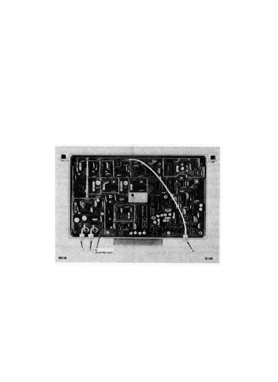
Figure 10-3. Receiver Parts Locator
10-2

 Loading...

