SINAD IN
3
A12 FRNT PN
INTERFACE
———(——
L
A9
PROCESSOR
6
3
CONT
A3 SCOP
ROL
E/DVM CONTRC
1 KHz
NOTCH FIL
)L
DET
DET
8521-38
——»• SINAD OUT
——- SINAD IN
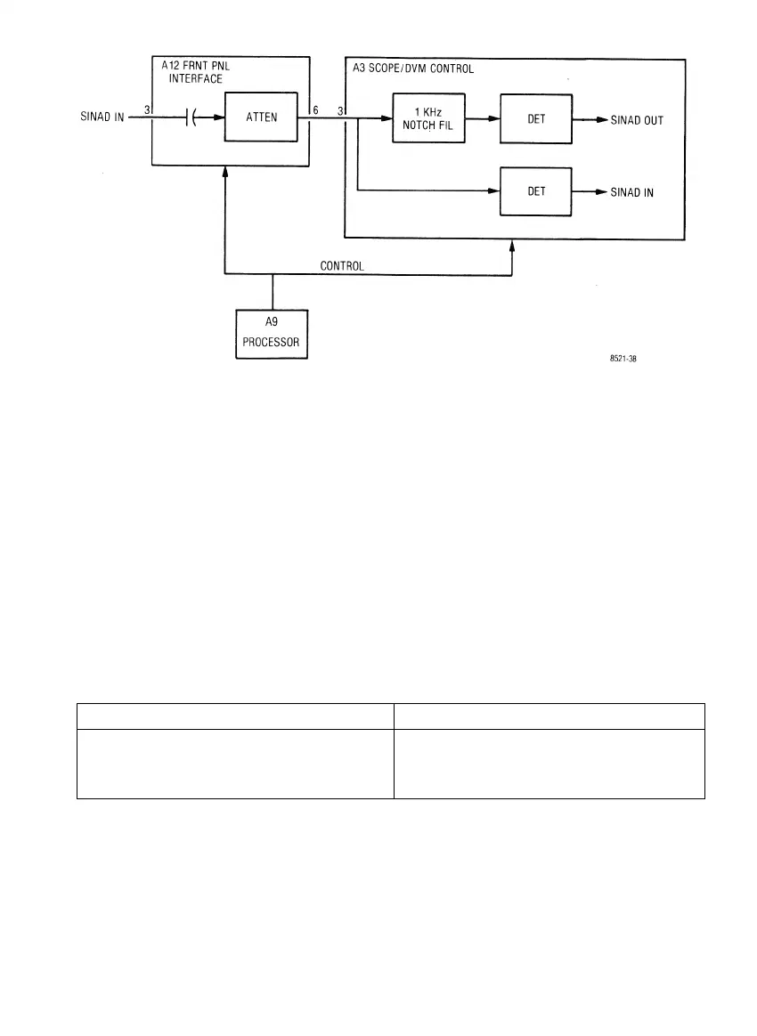
Figure 5-12. Sinad Meter Block Diagram
5-99. ALIGNMENT PROCEDURE
5-100. Introduction
5-101. This section provides a basic (para 5-105) and an extended (para 5-118) alignment procedure.
The basic procedure requires only the use of a calibrated oscilloscope. It is expected that the basic alignment
be performed whenever service work is performed. The extended alignment procedure requires module
extenders and a calibrated digital voltmeter in addition to the oscilloscope. The extended procedure should be
performed as required after servicing the system. All adjustments not covered in this procedure are to be
performed on suitable module test fixtures only.
5-102. Test Equipment Required
5-103. The test equipment or its equivalent listed in table 5-3 is required for the basic procedure. The
additional equipment required for the extended procedure is listed in table 5-4.
Table 5-3. Basic Test Equipment Required
Description
'Oscilloscope
Test Point Shorting Jumper
Nonmetallic Alignment Tool
Model
Motorola R1004A
*A R2001A is a suitable substitute
5-22

 Loading...

