Table 5-6. System Troubleshooting (Cont)
Test Paragraph Fault Troubleshooting Procedure
5-144
5-144
5-145
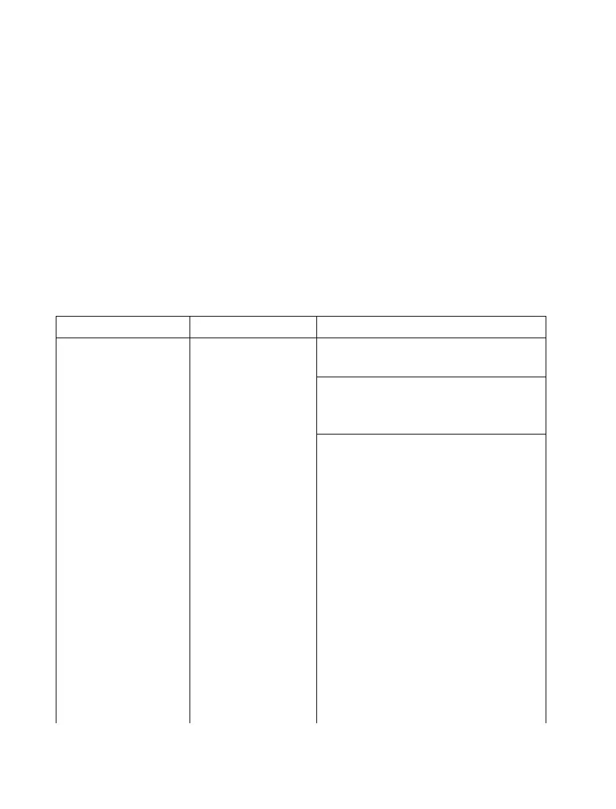
No spectrum analyzer sweep
Spectrum display is in error
No duplex output
1.. Check pin 6 of the RF Synthesizer module
(A5) for a 50 Hz square wave. If not present
replace the RF Synthesizer module.
2. If 50 Hz signal is present replace the Scope/ ,
DVM Control module (A3). '
1. Replace the Receiver module (A4).
1. Replace the RF Input module (A11).
Table 5-7. Test Point Identification
All test points are located near the top edge of the card and counted from left to right when facing the;
component side of the card.
!
Module
A2
Scope Amplifier
A3
Scope/DVM
Control
A6
Audio Synthesizer
Test Point No.
1
2
3
4
5
6
7
8
9
10
1
2
3
4
5
6
7
8
9
10
11
12
1
2
3
Signal Description
Horizontal Amp Input
Horizontal Deflection Plate
Horizontal Deflection Plate
Vertical Amp Input
Focus Tracking Voltage
Vertical Deflection Plate
Vertical Deflection Plate
Z-Axis Modulator Output
Intensity Tracking Voltage
Time Base Output
Vertical Character Sync
Negative Peak Detector Output
Gen Carrier Plus AM Level
Positive Peak Detector Output
Demodulated Calibrated Audio
Not Used
Ground
Multiplexed A/D Signal
Character Generator Reset
Ground
-8VDC
+8
VDC
Synth/DPL Audio
DPL Clock
Unfiltered DPL
5-42

 Loading...

