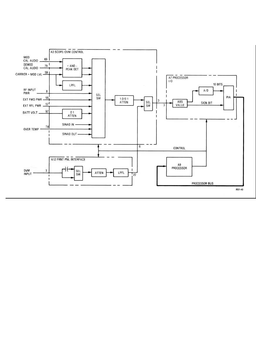
Figure 5-10. Digital Voltmeter (DVM) Block Diagram
5-73. Switching for the DVM input is contained on the Scope/DVM Control module (A3). One of ten internal
measurement points may be selected for measurement. The switching action is controlled by the processor
and is performed as required to obtain the information on the CRT. To keep the CRT information current, each
of the required measurements are made in sequence at an approximate rate of thirty per second. The net effect
is a multiplexing of the voltage information to the processor.
.5-74. Two modulation signals (MOD CAL AUDIO and CARRIER + MOD LVL) and a demodulated signal
(DEMOD CAL AUDIO) are made available to the peak detectors. Positive and negative peak determination of
the selected signal enables the processor to determine the level of modulation.
5-75. A Lowpass Filter (LPFL) removes the DC component from the CARRIER + MOD LVL signal so that the
generate RF output level can be determined. Refer to paragraph 5-30.
5-18

 Loading...

