2. Set FUNCTION switch to Gen. and DISPLAY switch to Gen/Mon Mtr.
3. Select frequency from RF memory table or enter directly from keyboard.
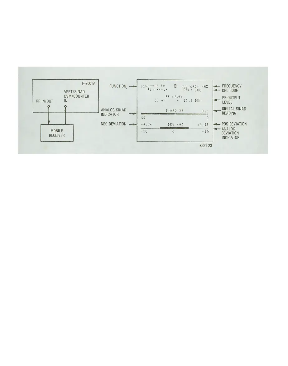
4. Adjust 1 kHz level for 3.0 kHz deviation and RF level for 12 dB SINAD indication. (The mobile
radio audio output may be set to the desired level using the DVM AC mode.)
5. Read receiver SINAD sensitivity in microvolts or dBm.
R-2001A
VERT/SINAD
OVM/COUNTER
RF IN/OUT IN
^-H——
MOBILE
RECEIVER
NEG DEVIATION -»•
FUNCTION -—
ANALOG SINAD
INDICATOR --*•
;EI."'-'E
Ff
B
•
1?;
.c4;
1
:
11H;
PL •••-,- DPL- OOCi
FF LEVEL
1-
•'-
-
1-.5
tE.n
I!"
6
:' I'E O.:'
;•:'
1:1
-•l.£4 tE'.; ' ••: " .EC.
-10
'.
- 11
-- FREQUENCY
—- DPL CODE
RF OUTPUT
LEVEL
DIGITAL SINAD
READING
<- POS DEVIATION
——ANALOG
DEVIATION
INDICATOR
8521-23
Figure 4-8. Test Setup for FM Receiver Sensitivity Using Generator and SINAD Meter with CRT Display
b. Test pager decode and alert function, and demonstrate simultaneous modulation.
1. Set FUNCTION switch to Gen and DISPLAY to Tone Mem.
2. Select pager frequency from RF memory table or enter directly from keyboard.
3. Enter pager tone code frequencies and select desired time sequence in memory table.
4. Activate and adjust Code Synth. Lvl. for 3.3 kHz deviation on Gen/Mon Mtr. display. (5 kHz
system)
NOTE
Timing sequences 1 through 4 are preset and can not be changed. Timing
sequences 5 through 8 are keyboard programmable for testing other pager types,
upper and lower timing limits, or future schemes.
4-18

 Loading...

