5-120. Character Generator
1. Perform the Basic Alignment Procedure of para 5-105.
2. Turn the R2001A off and extend the Scope/DVM Control Board using the 100 pin extender card.
3. Turn the R2001A on and select the Monitor FM Function and the Gen/Mon Mtr Display.
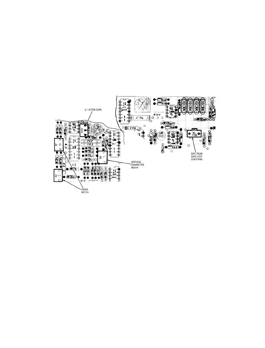
4. Adjust the Horizontal Character Sweep Width Potentiometer on the Scope/DVM Control Board
(Figure 5-20) so that the right-hand edge of the CRT character display is approximately 4.2 graticule
divisions to the right of the graticule center line.
Figure 5-20. Scope/DVM Control Char Sweep and Sinad Alignment Points
5. Adjust the Vertical Character Sweep Width Potentiometer on the Scope/DVM Control Board (FigureS-
20) so that the bottom edge of the CRT display is approximately 3.3 graticule divisions below the
graticule center line.
6. Turn the system power off and reinstall the Scope/DVM Control Board into the R2001A,
5-121. Sinad Notch Filter
1. Turn the R2001A off and extend the Scope/DVM Control Board using the 100 pin extender card.
2. Turn the R2001A on and select the Generate FM Function and the Gen/Mon Mtr Display.
3. Set the Modulation Switch and the Ext. Level Control to their off positions. Set the BW Switch to the
Narrow position and adjust the 1 kHz Level Control for a 20 kHz deviation reading on the CRT display.
4. Connect the Mod Out Jack on the fron panel to the Vert/Sinad/DVM/Counter Input Jack on the front
panel.
5-30

 Loading...

