5-14. MAJOR ASSEMBLIES
5-15. The Communication System Analyzer is designed for ease of maintenance. Most of the circuitry is on
seven plug-in circuit boards. A list of all subassemblies is given in table 5-1. The assembly locations are shown
in figures 5-1 and 5-2.
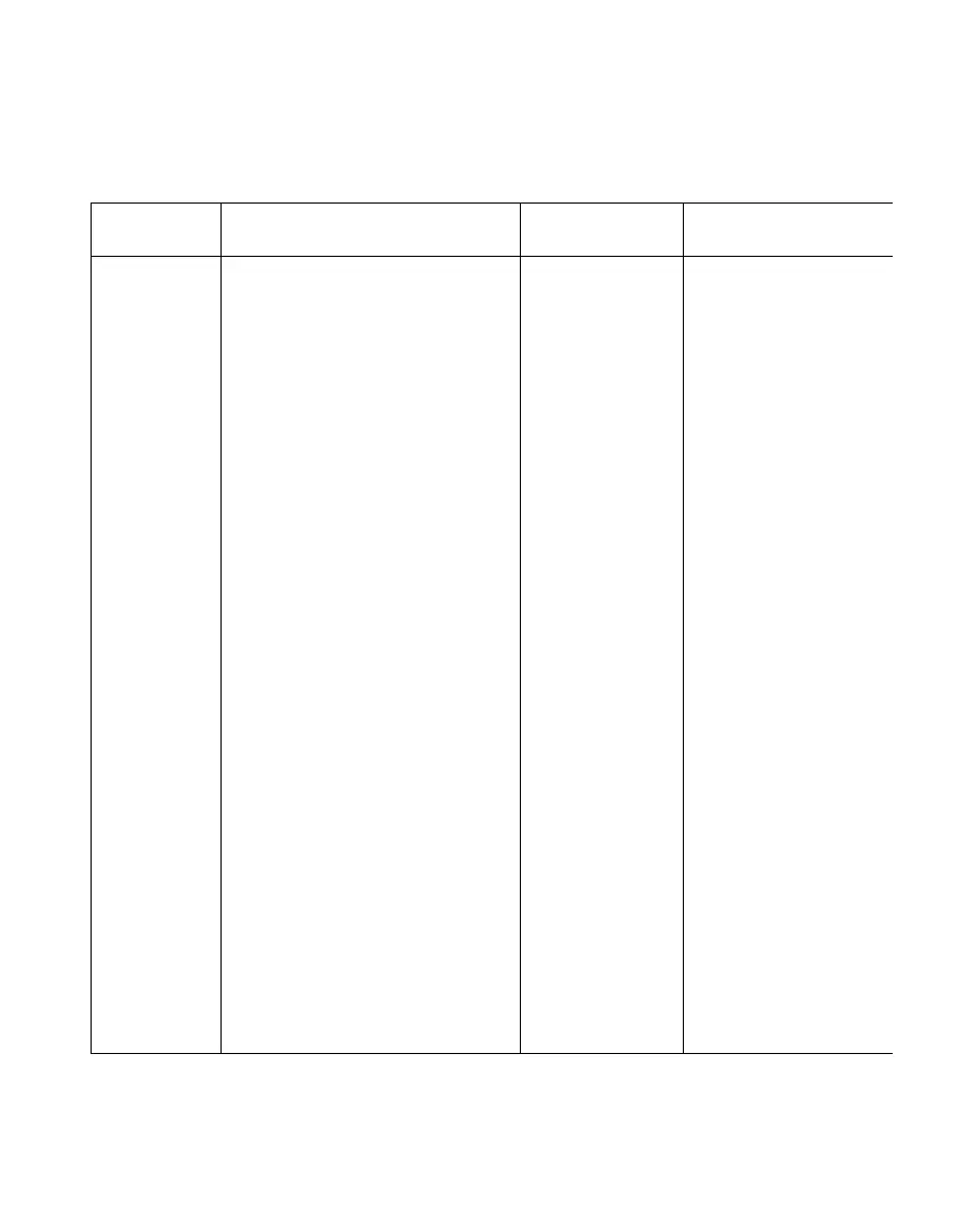
Table 5-1. List of Subassemblies
Ref.
Des.
A1
A2
A3
A4
A5
A5A*
A5B*
A6
A7
A8
A9
A10
A11
A11A1*
A11A2*
A11A3*
A12
A13
A14
Item
Low Voltage Power Supply Module
Scope Amplifier Module
Scope/DVM Control Module
Receiver Module
Synthesizer Module
Digital Synthesizer Card
RF Synthesizer Card
Audio Synthesizer Module
Processor Input/Output Module
IEEE Bus Module (Optional)
Microprocessor/Character
Generator Module
High Voltage Power Supply Module
RF Input Module
Protection/Power Meter Card
Converter/Wide Band Amplifier
Card
Offset Generator Card
Front Panel Interface Module
Frequency Standard Module
Front Panel Assembly
Motherboard Assembly
Part Number
As Labeled
01-P00422N001
01-P00413N001
01-P00409N001
01-P00389N001
01-P00385N001
01-P00358N001
01-P00386N001
01-P00426N001
01-P00405N001
01-P00430N001
01-P00401N001
01-P00417N001
01-P00394N001
01-P00400N001
01-P00398N001
01-P00399N001
01-P00421N001
01-P00368N001
01-P00366N001
01-P00441N001
Replacement
Order Part No.
RTP-1000A
RTC-4007A
RTC-4008A
RTL-1002A
RTC-1001A
RTC-4009A
RTC-4010A
RTC-4011A
RTC-4012A
RTC-4013A
RTC-4014A
RTP-1001A
RTC-1002A
RTL-4061A^
RTC-4015A(-
RTC-4016A^)
RTL-4045A
RTL-1004A
01-80304A42
RTL-4060A
'These items are solder-in submodules listed for reference purposes. These cards are not normally repaired
or replaced individually.
5-3

 Loading...

