8. Repeat paragraphs 5-119.3 and 5-119.4.
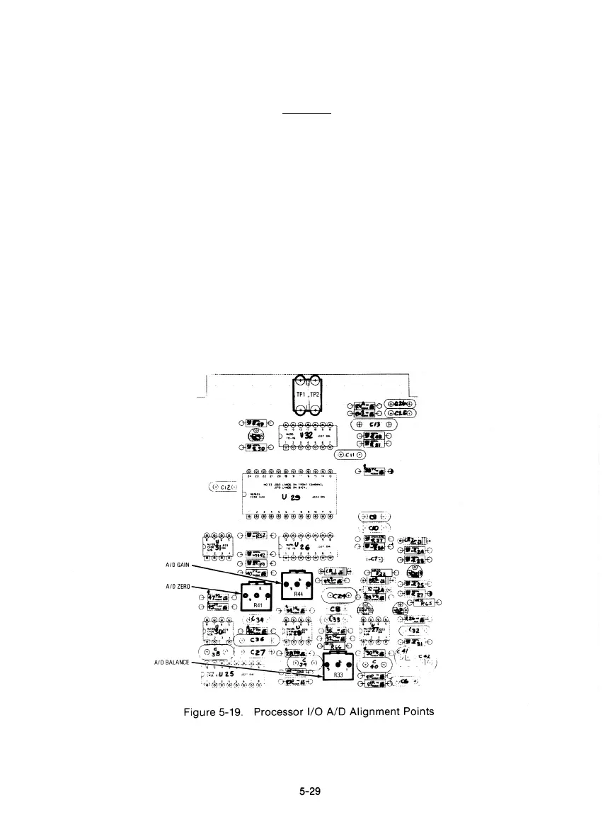
9. Disconnect the external DVM. With the DVM input jack still shorted adjust the A/D Zero Potentiometer
on the I/O Board (Figure 5-19) for a O.tfVDC'reading on the R2001ACRT display.
CAUTION
Do not use the card extender while aligning the Processor I/O board.
10. Remove the short from the DVM Input and connect the DVM Input to TP 12 of the Scope/DVM Control
Board.
11. Adjust the A/D Gain Potentiometer on the Processor I/O Board (Figure 5-19) for a DVM reading on the
CRT equal to the voltage measured at TP 12 with the external DVM for paragraph 5-119.6.
12. Connect the external DVM to TP11 of the Scope/DVM Control Board and chassis ground. Note the
DVM reading for TP11.
13. Disconnect he external DVM from TP11 and connect the DVM Input Jack on the front panel to TP11 of
the Scope/DVM Control Board.
14. Adjust the A/D Balance Potentiometer on the Processor I/O Board (Figure 5-19) for a DVM reading on
the CRT equal to the voltage measured at TP11 with. the external DVM in step 13.
AID BALANCE
Figure 5-19. Processor I/O A/D Alignment Points
5-29
s ® ® a ° '''^"gj ° ^ i',} t») @ ®^;^
;
A»DGAIII__, Q I——SIP -
J
^ "'- • "

 Loading...

