SECTION3
OPERATION
3.1.0 INTRODUCTION
To
become
proficient, an
operator
must know
th
e equip-
ment
and
its capabilities. Before
operating
the
service
monitor. carefully study
the
purpose
and
function
of
each
switch and indi
cator
described
here
and become familiar
with
the
operating
procedures
given.
3.1.1 SWITCH
AND
INDICATORS
See
figures 1,
2,3,4,5,6
,
7,
and
8 for
the
location
of
assemblies, controls and indicators
on
the
front
of
the
service monitor.
3.2.0
GENERAL
The
service
monitor
is
the
radio
communication techni-
cian's universal tool. It
is
required
to
service
and
main-
tain most
AM,
FM
and
CW
two-way
radio
equipment
and
needs
to
provide accurate measurements, have
dur-
ability
and
offer
fast, efficient use. This service
monitor
was designed
to
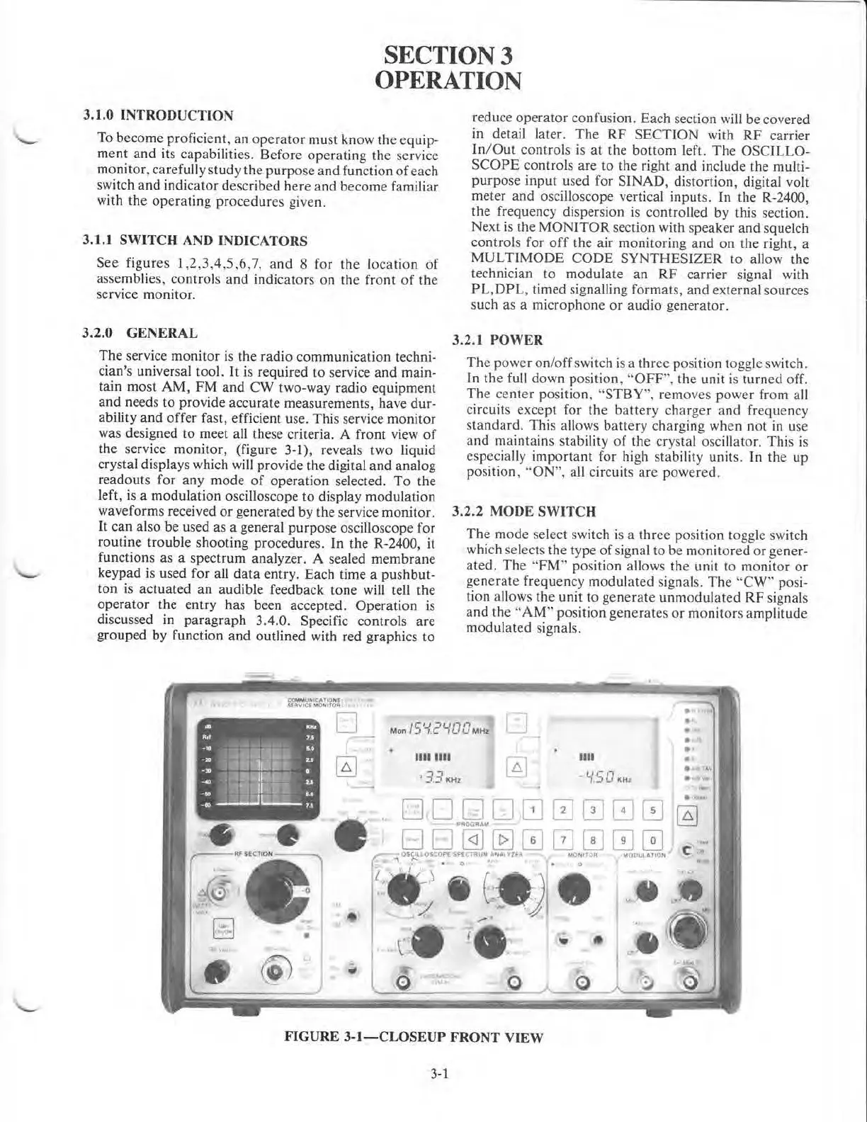
meet all these criteria. A
front
view
of
the service monitor, (figure
3-l),
reveals two liquid
crystal displays which will provide the digital
and
analog
readout
s for
any
mode
of
operation
selected.
To
the
left
is a modulation oscilloscope
to
display modulation
wa~eforms
received
or
generated
by
the service
monitor.
lt
can
also
be
used as a general
purpose
oscilloscope for
routine
trouble
shooting
procedures.
In
the
R-2400, it
functions as a
spectrum
analyzer. A sealed
membrane
keypad is used
for
all
data
entry. Each time a
pushbut-
ton
is
actuated
an
audible feedback
tone
will tell
the
operator
the
entry has been accepted. Operation is
discussed in
paragraph
3.4.0. Specific controls
are
grouped by function
and
outlined with red graphics
to
reduce
operator
confusion. Each section will be covered
in detail later.
The
RF
SECTION
with
RF
carrier
In
/
Out
controls is
at
the
bottom
left.
The
OSCILLO-
SCOPE
controls
are
to
the
right
and
include the multi-
purpose
input
used for
SINAD,
distortion, digital volt
meter
and
oscilloscope vertical inputs.
In
the
R-2400,
the
frequency dispersion
is
controlled by this section.
Next
is
the
MONITOR
section with speaker
and
squelch
controls for
off
the
air monitoring
and
on
the
right, a
MULTIMODE
CODE
SYNTHESIZER
to
allow
the
technician
to
modulate
an
RF
carrier signal with
PL
,
DPL
, timed signalling
formats,
and
external sources
such as a
microphone
or
audio generator.
3.2.1 POWER
The
power
on/
off
switch is a
three
po
si
tio~
t?ggle switch.
In
the full down position, "
OFF
",
the
umt
IS
turned
off.
The
center
position.
''
STBY
", removes
power
from all
circuits
except
for
the
battery
charger
and
frequency
standard.
This
allows
battery
charging when not in use
and
maintains stability
of
the
crystal oscillator.
This
is
especially
important
for high stability units. In
the
up
position, '·ON", all circuits
are
powered.
3.2.2 MODE SWITCH
The
mode
select switch
is
a
three
position toggle switch
which selects
the
type
of
signal
to
be
monitored
or
gener-
ated.
The
"
FM
''
position allows
the
unit
to
monitor
or
generate
frequency
modulated
signals.
The
"C
W". posi-
tion allows
the
unit
to
generate
unmodulated
RF
s1gnals
and
the
"
AM"
position
ge
n
erates
or
monitors
amplitude
modulated
signals.
1111 1111
•33~tH~
..
.
FIGURE
3-1-CLOSEUP
FRONT VIEW
3-1

 Loading...

