+9.5.&
300Hz 1000Hz
2500Hz 3000Hz
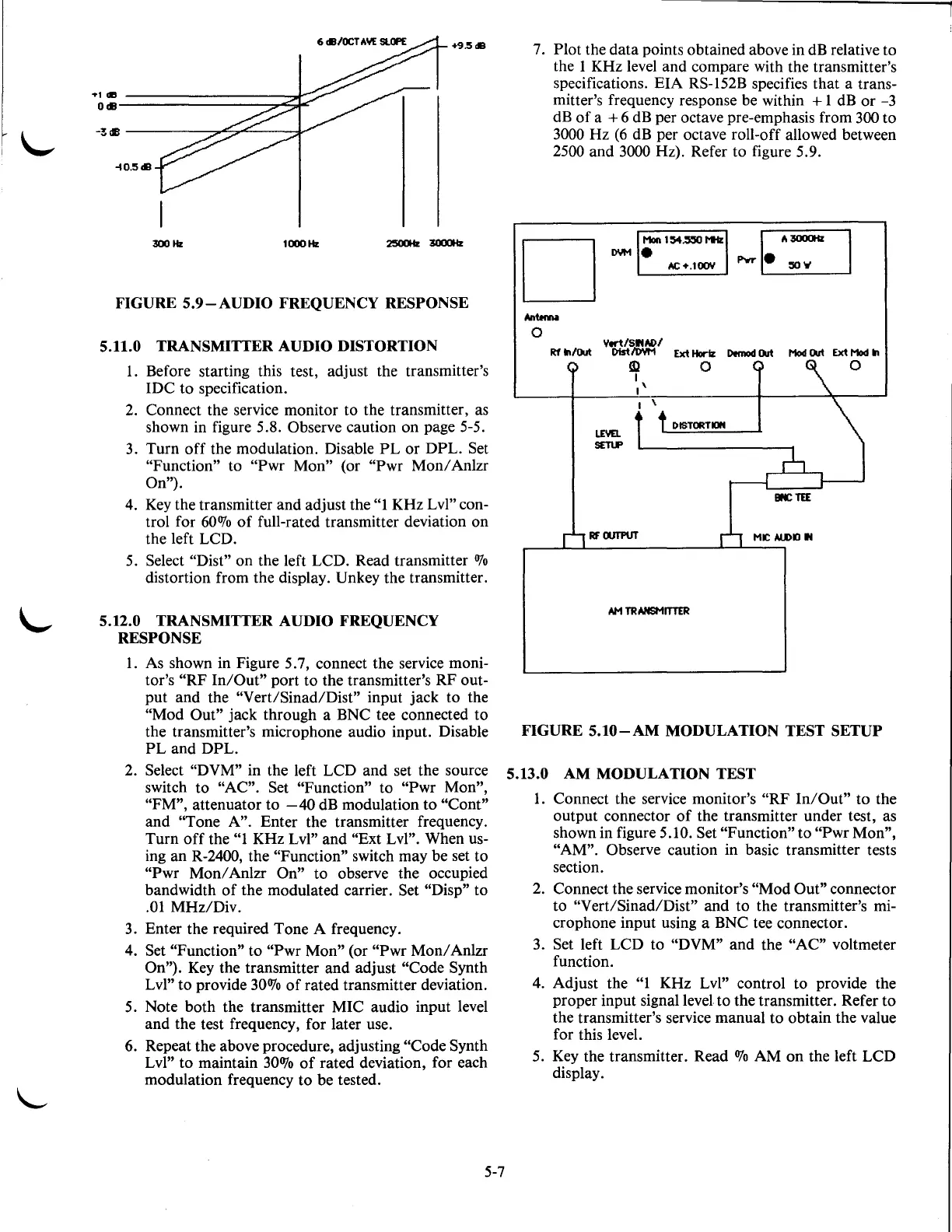
FIGURE
5.9-AUDIO
FREQUENCY RESPONSE
5.11.0
TRANSMITTER
AUDIO
DISTORTION
1.
Before starting this test, adjust the transmitter's
IDC
to
specification.
2.
Connect the service monitor
to
the transmitter, as
shown in figure 5.8.
Observe caution on page 5-5.
3.
Turn
off
the modulation. Disable
PL
or
DPL.
Set
"Function" to
"Pwr
Mon"
(or
"Pwr
Mon/
Anlzr
On").
4. Key the transmitter and adjust the
"1KHz
Lvl" con-
trol for
600Jo
of
full-rated transmitter deviation on
the left LCD.
5. Select
"Dist'' on the left LCD. Read transmitter
OJo
distortion from the display. Unkey the transmitter.
5.12.0 TRANSMITTER AUDIO FREQUENCY
RESPONSE
1.
As shown in Figure 5.7, connect the service moni-
tor's
"RF
In/Out"
port
to
the transmitter's RF out-
put
and the "Vert/Sinad/Dist" input jack
to
the
"Mod
Out"
jack through a BNC tee connected
to
the transmitter's microphone audio input. Disable
PL
and
DPL.
2. Select "DVM" in the left LCD
and
set the source
switch
to
"AC". Set "Function" to "Pwr Mon",
"FM",
attenuator
to
-40
dB modulation
to
"Cont"
and
"Tone A". Enter the transmitter frequency.
Turn
off
the
"1
KHz Lvl" and "Ext Lvl". When us-
ing an
R-2400, the "Function" switch may be set
to
"Pwr
Mon/
Anlzr
On"
to
observe the occupied
bandwidth
of
the modulated carrier. Set "Disp"
to
.01
MHz/Div.
3. Enter the required Tone A frequency.
4. Set
"Function"
to
"Pwr
Mon" (or
"Pwr
Mon/
Anlzr
On"). Key the transmitter
and
adjust "Code Synth
Lvl"
to
provide
300Jo
of
rated transmitter deviation.
5. Note
both
the transmitter MIC audio input level
and
the test frequency, for later use.
6. Repeat the above procedure, adjusting
"Code Synth
Lvl"
to
maintain 30%
of
rated deviation, for each
modulation frequency
to
be tested.
5-7
7.
Plot the
data
points obtained above in dB relative to
the 1 KHz level and compare with the transmitter's
specifications.
EIA
RS-152B specifies that a trans-
mitter's frequency response be within
+ 1 dB
or
-3
dB
of
a + 6 dB per octave pre-emphasis from 300
to
3000 Hz
(6
dB per octave roll-off allowed between
2500 and
3000Hz).
Refer to figure 5.9.
D
Moll 1
:54~
!'liz
DYM.
AC+.100Y
Ytrt./SitAD/
Rf
In/Out
Dis11DYM
Ext Horlz
Demod
Ou1
Mod
Ou1
Ext
Mod
In
LE\IEL
SETLP
!3:1
I
•'
RFOUTPUT
0 0
DISTORTION
MIC
ALOKJ
It
AM
TRANSMITTER
FIGURE
5.10-AM
MODULATION TEST SETUP
5.13.0
AM
MODULATION TEST
1.
Connect the service monitor's
"RF
In/Out"
to
the
output connector
of
the transmitter under test, as
shown in figure
5.1
0. Set "Function"
to
"Pwr
Mon",
"AM". Observe
caution in basic transmitter tests
section.
2. Connect the service monitor's
"Mod
Out"
connector
to
"Vert/Sinad/Dist" and
to
the transmitter's mi-
crophone input using a BNC tee connector.
3. Set left LCD to
"DVM" and the
"AC"
voltmeter
function.
4. Adjust the
"1
KHz Lvl" control to provide the
proper input signal level
to
the transmitter. Refer
to
the transmitter's service manual
to
obtain the value
for this level.
5. Key the transmitter. Read
OJo
AM
on
the left LCD
display.

 Loading...

