6.
When using the service monitor's "RF
In/Out"
port
in the
"Pwr
Mon/
Anlzr On" mode, there
is
no
directly connected signal path to the spectrum
analyzer receiver. Instead, the signal path
is
loosely
coupled through internal capacitance. Thus, a
signal
of
a given power level at a low frequency
will
appear to be
of
greater power at a higher fre-
quency. Hence, a transmitter's harmonic power
will
appear greater than it really is, relative to the level
of
the carrier display. LEVEL ACCURACY OVER
WIDE FREQUENCY RANGES IN THE "Pwr
Mon/Anlzr On" MODE
IS
NOT SPECIFIED.
Refer to page
5-6
for a recommended procedure.
7.
When using the spectrum analyzer feature, the
HORIZ and VERT vernier controls MUST BE IN
THE
"Cal" POSITIONS. Failure to do this may
result in an uncalibrated display.
D-~·~-
14
I
0.70u41
MOIIl£
REC£1YER
""
......
0
Vert/SINAD/
Spo
.....
Rf ln/l:llt:
l);stii>I/H
Ext Horir:
.......
Out
Hod
Out
Ext Hod
In
p
p
0 0
0
0
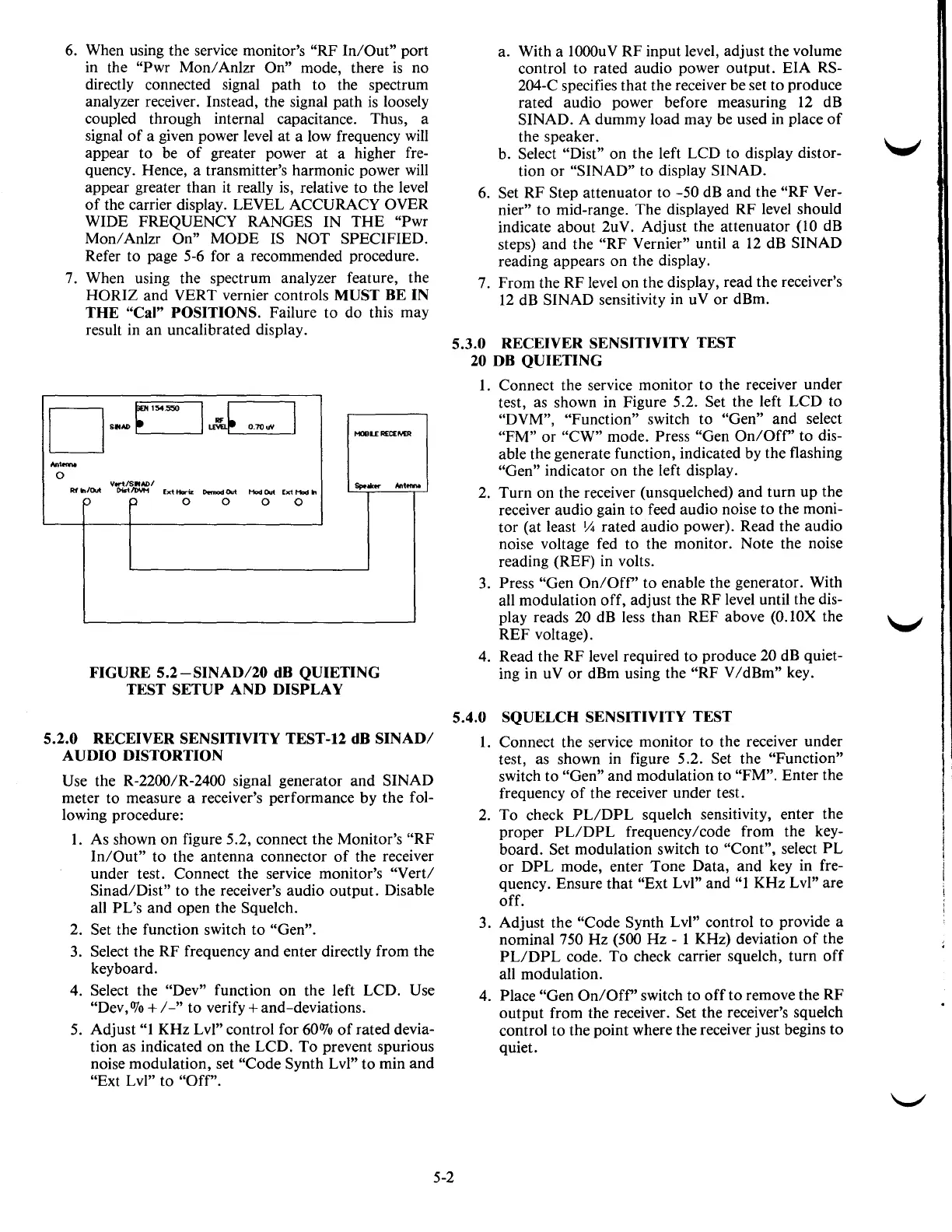
FIGURE
5.2-SINAD/20
dB QUIETING
TEST SETUP AND DISPLAY
Ant
.....
5.2.0 RECEIVER SENSITIVITY TEST-12 dB
SINAD/
AUDIO DISTORTION
Use
the R-2200/R-2400 signal generator and SINAD
meter to measure a receiver's performance by the fol-
lowing procedure:
1.
As shown on figure 5.2, connect the Monitor's "RF
In/Out"
to the antenna connector
of
the receiver
under test. Connect the service monitor's
"Vert/
Sinad/Dist" to the receiver's audio output. Disable
all
PL's and open the Squelch.
2.
Set the function switch to "Gen".
3. Select the RF frequency and enter directly from the
keyboard.
4.
Select the "Dev" function on the left LCD. Use
"Dev,
OJo
+I-"
to verify+ and-deviations.
5. Adjust
"1
KHz Lvl" control for 60%
of
rated devia-
tion as indicated on the LCD.
To
prevent spurious
noise modulation, set
"Code Synth Lvl" to min and
"Ext Lvl" to "Off".
a. With a 1000uV RF input level, adjust the volume
control to rated audio power output. EIA
RS-
204-C specifies that the receiver be set to produce
rated audio power before measuring
12
dB
SINAD. A dummy load may
be
used in place
of
the speaker.
b.
Select "Dist'' on the left LCD to display distor-
tion or "SINAD" to display SINAD.
6. Set RF Step attenuator to -50 dB and the
"RF
Ver-
nier"
to mid-range. The displayed RF level should
indicate about 2uV. Adjust the attenuator
(10
dB
steps) and the
"RF
Vernier" until a
12
dB SINAD
reading appears on the display.
7. From the RF level
on
the display, read the receiver's
12
dB SINAD sensitivity in
uV
or
dBm.
5.3.0 RECEIVER SENSITIVITY TEST
20
DB QUIETING
1.
Connect the service monitor to the receiver under
test, as shown in Figure 5.2.
Set the left LCD to
"DVM", "Function" switch to "Gen" and select
"FM"
or
"CW" mode. Press "Gen
On/Off'
to dis-
able the generate function, indicated by the flashing
"Gen" indicator on the left display.
2.
Turn on the receiver (unsquelched) and turn up the
receiver audio gain to feed audio noise to the
moni-
tor (at least
Y4
rated audio power). Read the audio
noise voltage fed to the monitor. Note the noise
reading (REF) in volts.
3.
Press "Gen
On/Off'
to enable the generator. With
all modulation off, adjust the RF level until the
dis-
play reads
20
dB less than REF above (O.lOX the
REF voltage).
4. Read the RF level required to produce
20 dB quiet-
ing in
uV
or dBm using the "RF V
/dBm"
key.
5.4.0 SQUELCH SENSITIVITY TEST
1.
Connect the service monitor to the receiver under
test, as shown in figure 5.2.
Set the "Function"
switch to "Gen" and modulation to "FM". Enter the
frequency
of
the receiver under test.
2.
To check
PL/DPL
squelch sensitivity, enter the
proper
PL/DPL
frequency/code from the key-
board. Set modulation switch to "Cont", select
PL
or
DPL
mode, enter Tone Data, and key in fre-
quency. Ensure that "Ext Lvl" and
"1
KHz Lvl" are
off.
3. Adjust the
"Code Synth Lvl" control to provide a
nominal
750 Hz (500 Hz - 1 KHz) deviation
of
the
PL/DPL
code. To check carrier squelch, turn
off
all modulation.
4.
Place "Gen
On/Off'
switch to
off
to remove the RF
output from the receiver.
Set the receiver's squelch
control to the point where the receiver just begins to
quiet.
5-2

 Loading...

