2.
Set the "Function" switch to "Pwr
Mon/
Anlzr
On" and attenuator to
-30
dB. Verify that the
display's center frequency reads the same as the
transmit frequency in step
A-7 above.
3.
Key
the transmitter and adjust the reject notch
adjustments on the duplexer receiver
leg
cavities
for minimum signal on the display. Change the
attenuator, as necessary, to keep the signal on the
display.
4.
Loosen the cavity reject adjustment nut and slide
it within its slot while watching the display.
Tighten the adjustment nut.
Be
careful not to
mistune the rejection adjustment. Fine tune the
rejection adjustment by turning the bandpass
knob a maximum
of
+/-15
degrees. This com-
pletes the duplexer receiver
leg
reject notch ad-
justment.
~
r---1
o-~,·~
.........
0
Rf
o./Out
~..=/
Ext-
Domod
Out
0 0 0
5llllt1POWOILOAD
Hod Otrt Ext Hod
k-1
0 0
\ !
RE.ECT
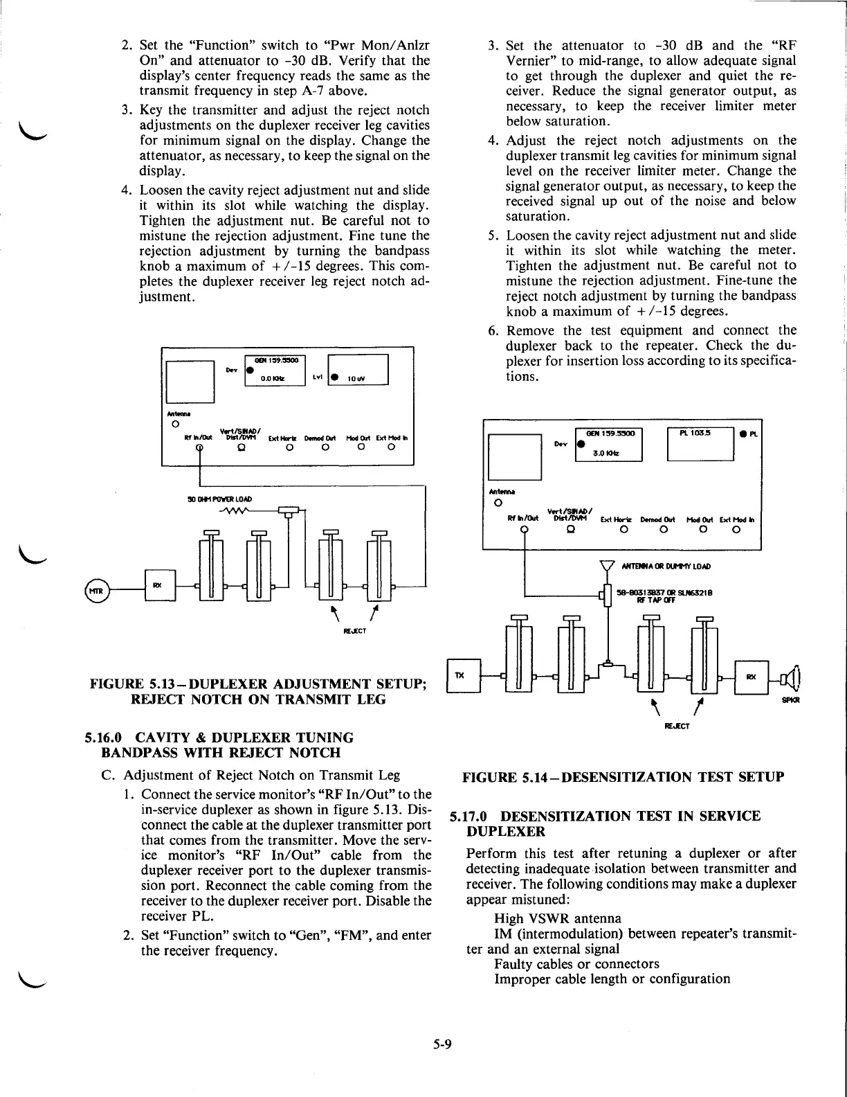
FIGURE
5.13-DUPLEXER
ADJUSTMENT SETUP;
REJECT NOTCH ON TRANSMIT LEG
5.16.0 CAVITY
&
DUPLEXER
TUNING
BANDPASS
WITH
REJECT
NOTCH
C. Adjustment
of
Reject Notch on Transmit Leg
1.
Connect the service monitor's
"RF
In/Out"
to the
in-service duplexer as shown in figure 5.13.
Dis-
connect the cable
at
the duplexer transmitter port
that comes from the transmitter. Move the serv-
ice
monitor's "RF
In/Out"
cable from the
duplexer receiver port to the duplexer transmis-
sion port. Reconnect the cable coming from the
receiver
to
the duplexer receiver port. Disable the
receiver PL.
2. Set
"Function" switch to "Gen", "FM", and enter
the receiver frequency.
3. Set the attenuator to
-30
dB
and the "RF
Vernier"
to mid-range, to allow adequate signal
to get through the duplexer and quiet the
re-
ceiver. Reduce the signal generator output, as
necessary, to keep the receiver limiter meter
below saturation.
4.
Adjust the reject notch adjustments on the
duplexer transmit
leg
cavities for minimum signal
level on the receiver limiter meter. Change the
signal generator output, as necessary, to keep the
received signal up out
of
the noise and below
saturation.
5.
Loosen the cavity reject adjustment nut and slide
it within its slot while watching the meter.
Tighten the adjustment nut.
Be
careful not to
mistune the rejection adjustment. Fine-tune the
reject notch adjustment by turning the bandpass
knob a maximum
of
+
/-15
degrees.
6.
Remove the test equipment and connect the
duplexer back to the repeater. Check the
du-
plexer for insertion loss according to its specifica-
tions .
~
D
o.v~
Nrtonno
0
v.rt/SrtN>/
Rf
In/Out
DistiDYM
Ext Horiz
Domod
Out
Hod
Out
Ext Hod
In
0 0 0 0 0
REJECT
FIGURE
5.14-DESENSITIZATION
TEST SETUP
5.17.0 DESENSITIZATION TEST IN SERVICE
DUPLEXER
5-9
Perform this test after retuning a duplexer or after
detecting inadequate isolation between transmitter and
receiver. The following conditions may make a duplexer
appear mistuned:
High VSWR antenna
IM (intermodulation) between repeater's transmit-
ter and an external signal
Faulty cables
or
connectors
Improper cable length or configuration

 Loading...

