SECTION4
OPERATING
INSTRUCTIONS
4.1.0 OPERATION
The operator may use the
LCD's
and
CRT
display to
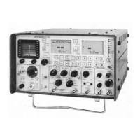
become familiar with the functions the Communication
Service Monitor
is
capable
of
performing. As a function
is
selected, its parameters are displayed
on
the LCD's.
4.2.0 POWER UP
4.2.1 PARAMETER MEMORY
The unit contains nonvolatile memory that stores the
most recently programmed values for the following pa-
rameters;
1.
Operating Frequency
2.
DPL
Code
3.
PL Frequency
4.
Tone A and B
a) Frequency
b) Duration
c) Delay
5. Deviation Alarm Limit
Also included in memory are the most recent state
of
the
following membrane keys;
1.
DEV
±
2.
RF
V/dBm
3. Display select arrows (left and right)
4.
DVM
AC/DC
5.
Code
Synthesizer
Modulation
select
arrow
(vertical)
WARNING Lithium Battery
The processor module within this system utilizes a
lithium battery as a memory keep-alive voltage source.
Do not mutilate
or
disassemble the battery cell. The
lithium metal
is
a very active material that burns in the
presence of water
or
high humidity.
Do
not put the
battery in fire, attempt to charge, heat above
100°C,
or
solder directly to the cell.
Do
not overdischarge the cell
to a reverse voltage greater than 3 volts. The battery may
burst and burn
or
release hazardous materials.
CAUTION Lithium Battery
Lithium batteries are classified as hazardous materials
and must be disposed
of
accordingly.
Do
not dispose
of
the battery by placing it in with the everyday trash.
Consult state and local codes for the appropriate disposal
procedure. Motorola will dispose of the battery if the
expended battery
is
returned in the replacement battery
container and by the same method that the new battery
came to you, send to: Motorola Inc., Return Goods
Department,
1313
East Algonquin Road, Schaumburg,
Ill. 60196.
4.2.2 DEFAULT PARAMETERS
The unit will initialize to the last active state unless the
battery
(P/N 60-83294N03) which powers the non-
volatile memory
is
faulty
or
has low output level due to
age
or
defect. (See the maintenance manual for battery
replacement.) Should this occur the initialized param-
eter
values will be;
Operating
Frequency-100 MHz
D
PL Code--000
PL Frequency-100
Hz
Tone A
a)
Frequency-!
kHz
b) Duration--0.5 Sec
c)
Delay--0.0 Sec
Tone B
a) Frequency-1.5 kHz
b)
Duration--0.5 Sec
c)
Delay--0.0 Sec
Deviation Alarm
Limit--0.0 kHz (alarm off)
DEV
± initial state
is
+
RF
V/dBm initial state
is
Volts
Display Select (left) initial state
is
SINAD
Display Select (right) initial state
is
RF
LVL
or
RF
PWR
DVM
AC/DC
initial state
is
AC
Code Synthesizer
Moduhtion
select initial state
is
TN
REM
NOTE: The Lithium Battery used for non-volatile
memory
is
included in every unit and
is
independent
of
the optional RTP-4021A Battery Pack Option.
All functions
that
are controlled by toggle switches, ro-
tary switches
or
potentiometers are initialized according
to the current positions
of
the switches.
4.3.0 GENERATE OPERATION
The Service Monitor generates
RF
frequencies for FM,
AM,
and CW transmissions covering a range
of
200kHz
to 1 GHz. To generate a signal the
"FUNCTION"
switch
is
placed in the
"GEN"
or
"HI
GEN"
position.
NOTE:
An
RF
protection circuit to protect against damage
due to inadvertent application
of
RF
power to the unit
is
provided.
4.3.1
OUTPUT LEVEL
Output
in the
"GEN"
function
is
available at the
"RF
IN/OUT" connector. Voltage output range
is
.1
uV to
200 u V into 50 ohms for direct connection to the antenna
input
of
the equipment under service.
Output
in the
"HI
GEN"
function
is
available at the antenna
BNC
connec-
tor
of
the unit. Voltage output range
is
200 u V to 1
VRMS. This is sufficient for transmission through an
antenna connected to the antenna connector.
4-1

 Loading...