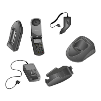
6/29/98 5
Theory of Operation
Special Logic Circuits
A brief description of special logic circuits
used in the StarTAC:
•
PAC IC
—A triple 8 bit DAC that controls
the PA bias and internal charger
•
Internal Charger
—The microprocessor is
capable of reading a Motorola Li Ion
battery with internal ROM to determine
optimum charging conditions. If no ROM
is detected, then the battery is charged as if
it were a NiCd or NiMH battery. The
internal charger is disabled during a call.
•
Vibrator Option
—Used as a silent alert
option for incoming calls. This option is
controlled by the SNAP IC and a external
driver circuit.
•
RF Switch Circuit
—An RF switch driver
and RF switch FET normally select the
internal antenna. The external RF
connection is selected if an antenna is
detected on the option connector.
 Loading...
