26 6/29/98
StarTAC 3000
Keypad Button Functions
Below is a description of the non-numeric
keys used during the keypad calibration
procedure:
Adjustment Procedure
Step 1.
Connect the test cable to a servicing
analyzer. Enter Manual Test mode.
Depress the # button. The display
should show the ’ prompt.
Step 2.
Enter
11434#
via the keypad to
program the synthesizer for
channel 434.
Step 3.
To key the transmitter, enter
05#
.
TX Output Power Adjust
Step 4.
Enter
73#
. The portable display will
show step number “00” on the left
and the corresponding hex value
for the TX output power on the
right.
Step 5.
Using the
]
button to advance
through the power steps. Adjust
each of the power steps listed in
Table 6: “Output Power Levels” for
the values shown as indicated on
the servicing analyzer. Make
adjustments as described in step 6
and step 7.
Step 6.
Enter a 2-digit hexadecimal
number via the keypad. This
immediately updates the hex
power level value, and the output
power should change as indicated
on the analyzer.
If the new entry does not produce
the desired analyzer reading (i.e.
too high or too low):
a. Depress the
CLR
button and
enter another 2-digit number
OR
b. Use the
VOL
button to
incrementally increase the hex
value to obtain the desired
reading on the analyzer. (The
volume control may not be used
to decrease the hex value.).
Toggles display to next location;
on last program step, enters new
data into memory and exits
command.
Restores displayed location to
data originally programmed;
useful to erase keypad entry
errors.
Terminates command without
updating any memory locations.
*
CLR
END
#
or
NOTE
The 73# command is normally disabled.
Adjustment of Transmit Output Power is
not recommended. Consult Motorola for
information about enabling the 73#
Transmit Power Adjustment Procedure.
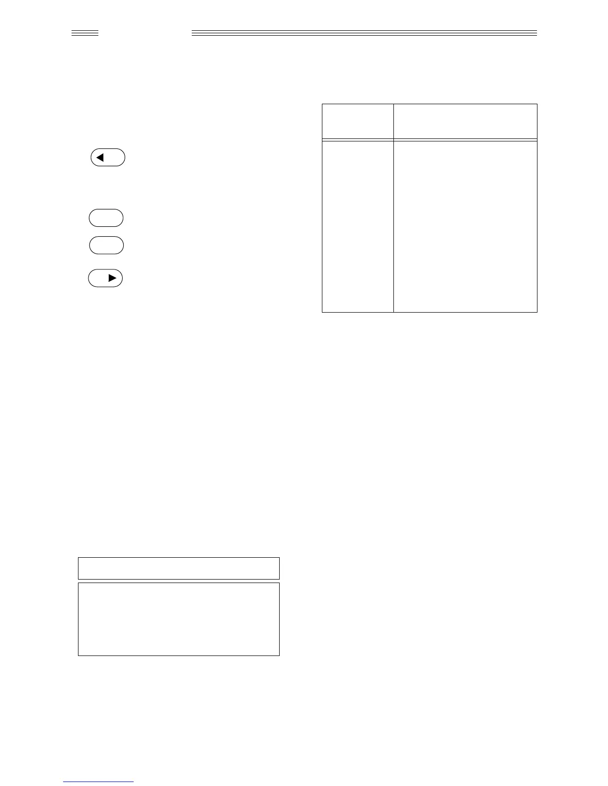
Table 6: Output Power Levels
Power Step
Output Power Spec
(at antenna port)
00
01
02
03
04
05
06
07
08
09
0A
0B
28 dBm
26 dBm
27 dBm
23.5 dBm
20 dBm
16 dBm
12 dBm
8 dBm
Do not adjust
Do not adjust
Do not adjust
Do not adjust

 Loading...