© 1998 Motorola, Inc. 3
THEORY OF OPERATION
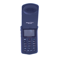
StarTAC 3000
Cellular Subscriber Group
Theory of Operation
Introduction
The StarTAC circuitry is contained on a
main PCB with an attached daughter board.
The main board contains RF and
Audio-Logic circuitry, and the daughter
board contains mostly Audio-Logic
circuitry. Refer to The A/L Functional Block
Diagram and page 48 and the RF Functional
Block Diagram Page 49 for circuit details.
Synthesizer Circuitry
StarTAC uses separate RX and TX synthe-
sizer loops. Each loop consists of a PLL in
the ANGUSS IC and a discrete Loop Filter
and VCO. The frequency reference for both
loops is the 16.8 MHz reference oscillator.
The ANGUSS IC also divides the reference
to 4.2 MHz for use by the SNAP IC.
Both synthesizers operate in a feedback and
phase detect fashion to provide a DC control
voltage to the VCO which selects and main-
tains the desired VCO output frequency in a
range of 979-1004 MHz for the RX VCO and
824-849 MHz for the TX VCO.
Receiver Circuits
The received RF signal enters the antenna or
external accessory port via a RF switch, and
passes through an 869-894 MHz saw filter.
The signal is amplified, filtered, and then
mixed with a 979-1004 MHz first local oscil-
lator signal. The mixer output is the 109.65
MHz first IF signal. The IF signal passes
through a crystal filter and then enters the
Low Voltage ZIF IC.
The LVZIF IC contains a 219.3MHz second
L.O. divided down by two, which is used to
mix the IF signal down to a frequency
modulated baseband signal. The baseband
signal then enters a programmable lowpass
filter which provides the required selectivity
for 30 kHz AMPS channels or for 10 kHz
NAMPS channels. The filtered baseband
signal is then up-mixed to 131.25 kHz using
a mixer and VCO internal to the Zero IF IC.
A discriminator internal to the Zero IF IC
demodulates the signal to become RX
Audio. RX Audio is routed to the
Audio-Logic section for further audio, SAT,
or data processing.
The receiver circuitry produces three
outputs which are routed to the
Audio-Logic daughter board:
• RX Audio
• RSSI (received signal strength indicator)
• Frequency Error
RX Audio can contain received voice audio,
high-speed data, low-speed data, DTMF,
and SAT signalling. (Low speed data
including DST and DSAT for NAMPS opera-
tion.)
RSSI is a DC voltage proportional to
received signal strength. RSSI is used when
scanning control channels to find the stron-
gest signal and to provide the Signal
Strength Meter user feature. RSSI is used in
NAMPS mode to initiate a Mobile
Requested Handoff.
Frequency Error is a logic signal used for
automatic-frequency-control (AFC), which
is employed in both AMPS and NAMPS
modes.
This circuit achieves better than 1.0 ppm
 Loading...