MAINTENANCE MTH800 TETRA Handportable Terminal / Basic Service Manual 6 - 13
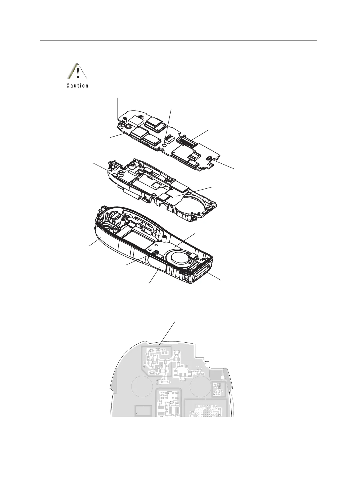
Figure 9 Main Board and Chassis & Display Assembly Removal and Installation
MAIN BOARD
UCM FASTENING
SCREW
CONNECTOR
(TO MAIN FLEX)
DISPLAY AND
CHASSIS
ASSEMBLY
CONNECTOR
(MAIN BOARD TO ACCESSORY)
MAIN FLEX
FRONT HOUSING
CONNECTOR
(TO MAIN FLEX)
AUDIO ASSEMBLY CAP
ACCESSORY CONNECTOR
ASSEMBLY
KEYPAD BOARD
When disassembling the main board
from the chassis, place the screwdriver’s flat tip
as close as possible to the corner
of the main board (side 1). Failing to do so might damage
one of the components shown in the main board (side 2) details,
and thus cause transmitter performance degradation.
C289
C290C291
C292
C293
C294
C500
C523
C533
C534
C537
C538
C539
C540
C541
C542
C544 C545
C546
C969
C978
C987
C988
C989
C2010
C2013
C2021
C5008
C5009
C5010
C5018
C5019
C5020
C5023
C5024
C5027
C5028
C5033
D500
D501
D5001
D5002
D5003
E502
3
2
3
4
2
5
FL2001
GPS_MCLK_EXT
L293
L294
L295
L296
L297
L508
L511
L512
L924
L2004
L2005
L2006
L2007
L5003
L5004
L5006
L5007
L5012
L5013
M201
R525
R2001
R5001
R5008
SH2002
SH2003
TP200
TP201
U502
A8
H8
U2000
improper disassembling of the mainboard
may damage these components

 Loading...