6809493A69-O May 18, 2005 35
Level 1 and 2 Service Manual Disassembly
Removing and Replacing the Motor Vibrator Assembly
1. Remove the battery cover, battery, SIM, antenna, rear housing, and
transceiver board assembly, flip assembly cover, and CLI lens cover as
described in the procedures.
2. Use the disassembly tool to unseat the flex connector and remove the camera
assembly flex connector from its socket.
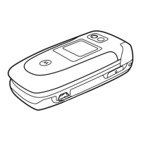
3. Carefully lift the motor/vibrator assembly and flex from the display assembly
(see Figure 17).
4. To replace, align the motor/vibrator connector to the connector socket.
5. Gently but firmly press the flex connector into it’s socket until properly seated.
6. Replace the camera assembly, display assembly, flip assembly bezel, flip
assembly, transceiver board, rear housing, antenna cap, SIM, battery, and
battery cover as described in the procedures.
G
The flexible printed cable (FPC) (flex) is easily damaged. Exercise extreme care when
handling.
Figure 17. Motor/Vibrator Assembly Removal
Vibrator Flex
Connector
Disassembly Tool
Display
Assembly
Motor/Vibrator
Assembly
 Loading...