©2005 Motorola, Inc.
V975/V980Table of Contents
iv Draft 1.0
Figure 2-10. WCDMA Modulation .............................................................................................................. 2-7
Figure 3-11. ACLR Screen ........................................................................................................................ 2-7
Figure 2-11. ACLR Screen ........................................................................................................................ 2-7
Non-Signaling Test Procedures (GSM/DCS/PCS) .................................................................. 2-8
Hardware Requirements .................................................................................................................................. 2-8
Software Requirements ................................................................................................................................... 2-8
Verify TX Power Output (GSM/DCS/PCS) ....................................................................................................... 2-8
Table 2-6. TX Power Limits ........................................................................................................................ 2-8
GSM RSSI ...................................................................................................................................................... 2-9
Non-signaling Test Procedures (WCDMA) ............................................................................ 2-10
Hardware Requirements ................................................................................................................................ 2-10
Software Requirements ................................................................................................................................. 2-10
Verify TX Power Output (WCDMA)................................................................................................................. 2-10
Table 2-7. WCDMA TX Power Output....................................................................................................... 2-10
Audio/Vibrator Test Procedures............................................................................................. 2-11
Vibrator Test .................................................................................................................................................. 2-11
Handset Mic/Speaker test ............................................................................................................................. 2-11
Mono Headset Mic/Speaker test ................................................................................................................... 2-11
Stereo Headset Mic/Speaker test .................................................................................................................. 2-12
Melody Speaker test ..................................................................................................................................... 2-12
Display Test Procedures ....................................................................................................... 2-13
Display Backlight Test ................................................................................................................................... 2-13
Display Color Test ......................................................................................................................................... 2-13
Figure 20. Eight Color Box Pattern .......................................................................................................... 2-13
Display Linearity Test .................................................................................................................................... 2-14
Figure 21. Grey Scale Block ................................................................................................................... 2-14
Display Flicker Test ....................................................................................................................................... 2-14
Figure 22. Zebra Pattern .......................................................................................................................... 2-14
Display Pixel Defect (Bright) ......................................................................................................................... 2-15
Display Pixel Defect (Dark) ........................................................................................................................... 2-15
LEDS and Keypad Backlight................................................................................................. 2-15
Keypad Backlight .......................................................................................................................................... 2-15
Camera Testing ..................................................................................................................... 2-16
Data Line Integrity Check .............................................................................................................................. 2-16
Camera Flash Check ..................................................................................................................................... 2-16
Theory of Operation ................................................................................................................... 3-1
V975/V980 Overview .............................................................................................................. 3-1
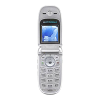
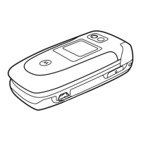
Figure 3-1. V975 Transceiver ..................................................................................................................... 3-1
Front End Module .................................................................................................................... 3-2
Figure 3-2. RF Top ..................................................................................................................................... 3-2
Figure 3-3. FEM Module (FL001) ............................................................................................................... 3-3
Table 3-1. FEM Truth Table ........................................................................................................................ 3-3
RF GSM Receiver ................................................................................................................... 3-4
BALUN ............................................................................................................................................................ 3-4
Figure 3-4. Balun Transformer .................................................................................................................... 3-4
BLUE MODULE IC (ALGAE) ........................................................................................................................... 3-4
Figure 3-5. ALGAE MB (Receiver) ............................................................................................................ 3-4
HARMONY GSM_RX (U100) ........................................................................................................................... 3-5
Figure 3-6. Harmony (GSM RX) ................................................................................................................ 3-5
 Loading...