Operation Section
36
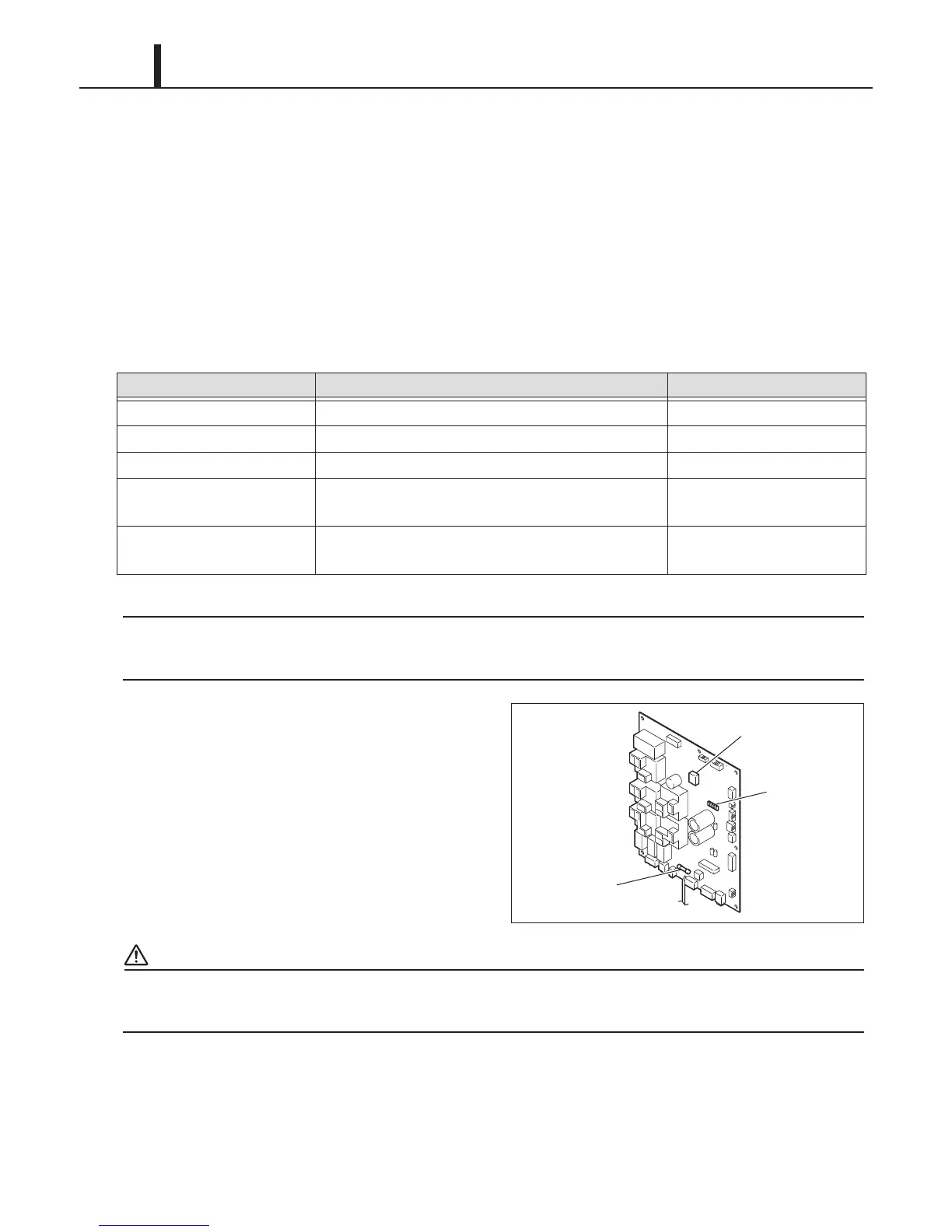
(3) Relay board
• The relay board is powered by 20 VAC from the secondary side of the step down transformer.
This voltage is then converted from 20 VAC to 12 VDC and supplied to the relay driver circuits
on the board. The 12 VDC is then converted again into 5 VDC and supplied to the
microprocessor, sensors, and switches on the relay board.
• The relay board contains surge protection circuit, AC power interruption and monitoring circuit,
fuse, and DIP switches (no function and are defaulted to the OFF positions). There are also 5
LEDs on the relay board that provides a visual tool to quickly diagnose problems on the relay
board. These LED's functional descriptions and status are listed in the table below.
The relay board must be serviced as a complete assembly. It has only one serviceable
component, the fuse. (see below)
• The relay board fuse provides protection
against damage to the step-down transformer.
It must be replaced with the exact type of fuse
or an equivalent.
Specifications:
- 1 A, 250 V
CAUTION
Failure to use the exact type of fuse could result in damage to the unit and/or to components. It
could also void the warranty of the unit.
LED Number Function and Description Normal Status
LED01 Indicates that the +5 VDC line is normal. Green LED is on.
LED02 Not in use. Not in use.
LED03 Indicates that the +12 VDC line is normal. Green LED is on.
LED04 Indicates that serial connection between the relay
board and the controller board is normal.
Yellow LED is blinking.
LED05 Indicates that serial connection between the relay
board and the controller board is normal.
Yellow LED is blinking.
ILL00865-00
Fuse
DIP Switch
LEDs
 Loading...