UC-8410A HW UM Hardware Connection Description
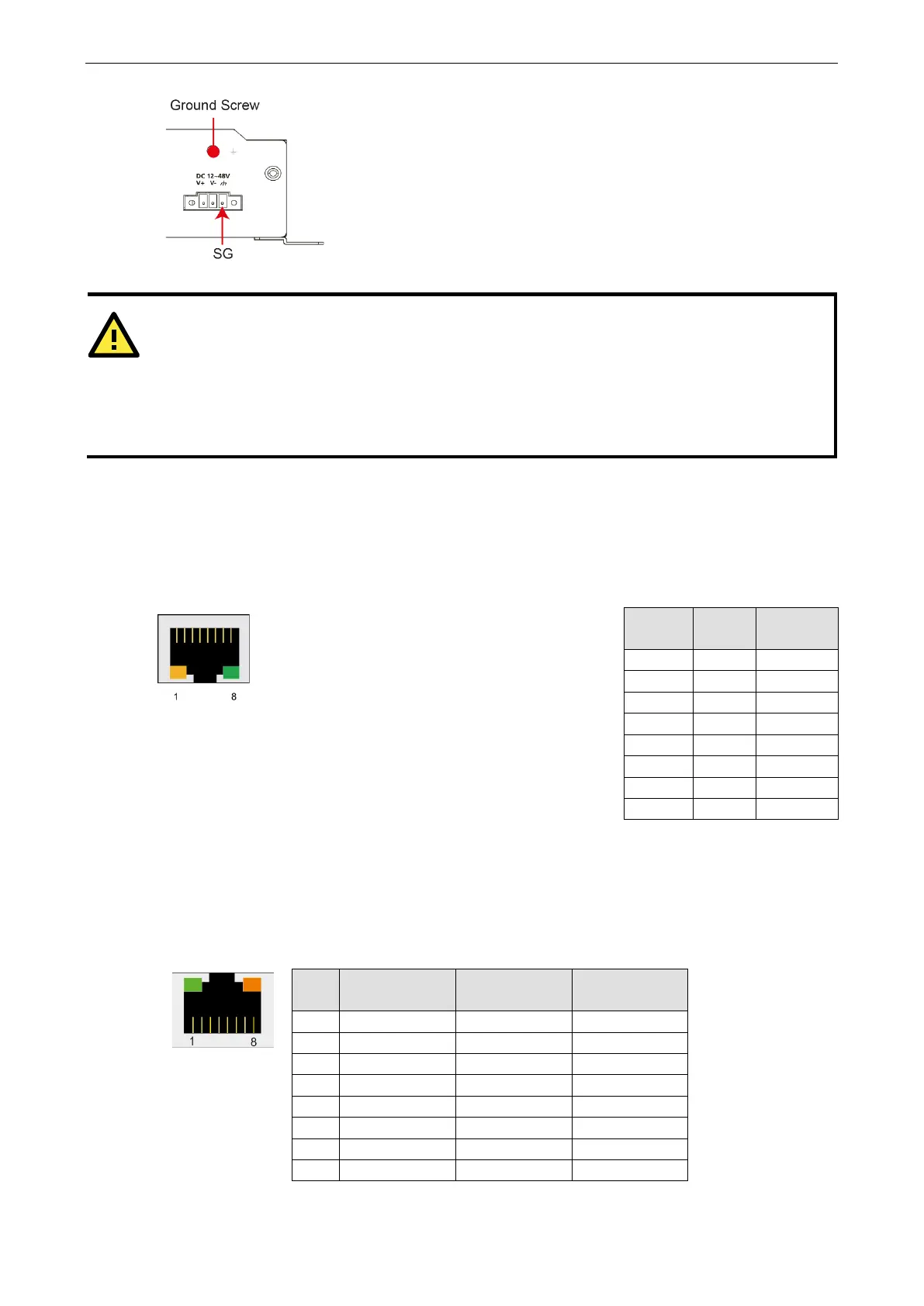
The Shielded Ground (sometimes called Protected Ground) contact is the
most contact of the 3-
pin power terminal block connector when viewed from
the angle shown here. Connect the SG wire to an appropriate grounded metal
surface.
An additional ground connector is provided just above the power
you can use for additional grounding protection.
-
type power cord is required in order to meet FCC emission limits and also to prevent interference
to nearby radio and television reception. It is essential that only the
power cord supplied w
ith the unit is used
to supply power
.
You are cautioned that changes or modifications not expressly approved by the party responsible for
compliance could void your authority to operate the equipment.
Connecting to the Network
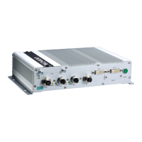
Connect one end of the Ethernet cable to one of the UC-8410A’s 10/100/1000 Mbps Ethernet ports (8-pin RJ45)
and the other end of the cable to the Ethernet network. If the cable is properly connected, the UC-8410A will
indicate a valid connection to the Ethernet in the following ways:
The lower right corner LED indicator maintains a
solid green color when the cable is properly connected
to a 100 Mbps Ethernet network. The LED will flash
on and off when Ethernet packets are being transmitted
PIN 10/100
Mbps
1000
Mbps
1 ETx+ TRD(0)+
2 ETx- TRD(0)-
3 ERx+ TRD(1)+
4 --- TRD(2)+
5 --- TRD(2)-
7 --- TRD(3)+
8 --- TRD(3)-
The lower left corner LED indicator maintains a
solid orange color when the cable is properly connected
network. The LED will flash
on and off when Ethernet packets are being transmitted
Connecting to a Serial Device
Use properly wired serial cables to connect the UC-8410A to serial devices. The UC-8410A’s serial ports (P1 to
P8) use 8-pin RJ45 connectors. The ports can be configured by software for RS-232, RS-422, or 2-wire RS-485.
The precise pin assignments are shown in the following table:
Pin RS-232
RS-422/
RS-485-4w
RS-485-2w
1 DSR – –
2 RTS TXD+ –
3 GND GND GND
4 TXD TXD- –
5 RXD RXD+ Data+
7 CTS – –
8 DTR – –