42
4. Mounting the Unit
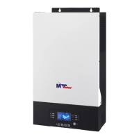
When installing multiple units, please follow below chart.
NOTE: For proper air circulation to dissipate heat, allow a clearance of approx. 20 cm to the side and approx.
50 cm above and below the unit. Be sure to install each unit in the same level.
5. Wiring Connection
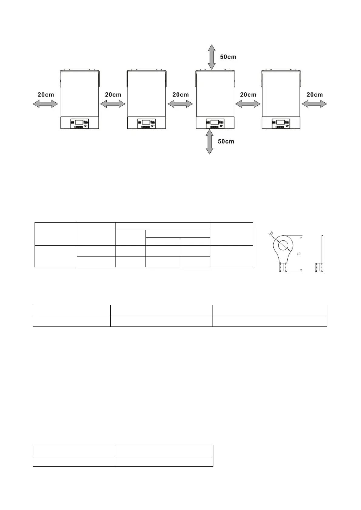
The cable size of each inverter is shown as below:
Recommended battery cable and terminal size for each inverter:
WARNING: Be sure the length of all battery cables is the same. Otherwise, there
will be voltage difference between inverter and battery to cause parallel inverters not
working.
Recommended AC input and output cable size for each inverter:
You need to connect the cables of each inverter together. Take the battery cables for example: You need to
use a connector or bus-bar as a joint to connect the battery cables together, and then connect to the battery
terminal. The cable size used from joint to battery should be X times cable size in the tables above. “X”
indicates the number of inverters connected in parallel.
Regarding AC input and output, please also follow the same principle.
CAUTION!! Please install the breaker at the battery and AC input side. This will ensure the inverter can be
securely disconnected during maintenance and fully protected from over current of battery or AC input. The
recommended mounted location of the breakers is shown in the figures in 5-1 and 5-2.
Recommended breaker specification of battery for each inverter:
*If you want to use only one breaker at the battery side for the whole system, the rating of the breaker
should be X times current of 1 unit. “X” indicates the number of inverters connected in parallel.
 Loading...