3 Product description
1510014218/00 EN
This chapter contains an overview of the design and function of the product.
3.1 Scope of delivery
The product is delivered as follows:
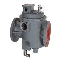
▪ Shutter valve
▪ O-ring gasket for tank-side mounting flange
▪ Bypass for resetting (available as an option)
3.2 Function description
The device is a protective device that, in the event of a steady loss of fluid
from the tank, stops the flow of fluid from the conservator to the tank, reduc-
ing the risk of fire and environmental pollution.
The device works automatically. If the flow rate from the conservator to the
tank exceeds a factory-set value, the device closes the pipe leading to the
tank.
If the device trips, a signal is sent via up to 2 reed-type switches (normally
open contact or change-over contact). The reed-type switches are con-
nected to the electrical controller and the monitoring circuit of the trans-
former.
Transformer operating phases
The conditions described in the following can arise during normal trans-
former operation and will not normally lead to the device closing the pipe:
▪ During the heating phase when the oil temperature increases, oil flows
from the tank to the conservator due to the expansion of the oil volume.
The flow rate is normally ≤30dm
3
/min.
▪ During the cooling phase when the oil temperature decreases, oil flows
from the conservator to the tank due to the contraction of the oil volume.
The flow rate is normally ≤30dm
3
/min.
Transformer error states
The device closes automatically if the following condition arises:
▪ If a tank leak arises, for example when a bushing fails or a pressure relief
device springs open and then does not close again correctly, oil flows
back from the conservator to the tank. The expected flow rate is normally
>>30dm
3
/min.
 Loading...