5 Mounting
2910014218/00 EN
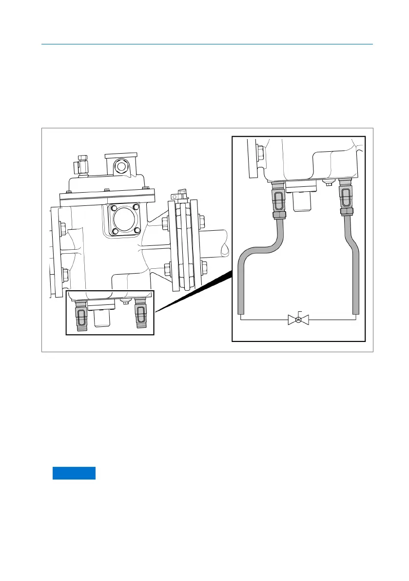
5.5.1 Installing the BPR (ball valve) bypass (optional)
The BPR bypass is operated via a ball valve.
As the BPR version, the device is equipped with two drain valves that are
positioned on the base of the housings. The pipe circuit will be connected to
these drain valves via ball valve.
Figure9: Example BPR pipe bypass
ü The material of the pipes is suitable for the insulating fluid and the temper-
ature range.
ü The length of the pipes have been adjusted to the operating height of the
ball valve.
ü The drain valves on the base of the device are open (normal operating
conditions).
1. Position the ball valve so that it can be reached from the floor.
2. NOTICE! Ensure that the ball valve is positioned so that the lever can be
actuated without hindrance.
3. Cut two pipes (external diameter 14mm, internal diameter 12mm) to a
length sufficient to connect the ball valve to the drain valves on the base
of the device.
 Loading...