7 Operation
38 10014218/00 EN
7.1 Alarm state
An alarm state shows that the device has tripped and that a signal has been
sent to the electrical controller and to the monitoring circuit of the trans-
former.
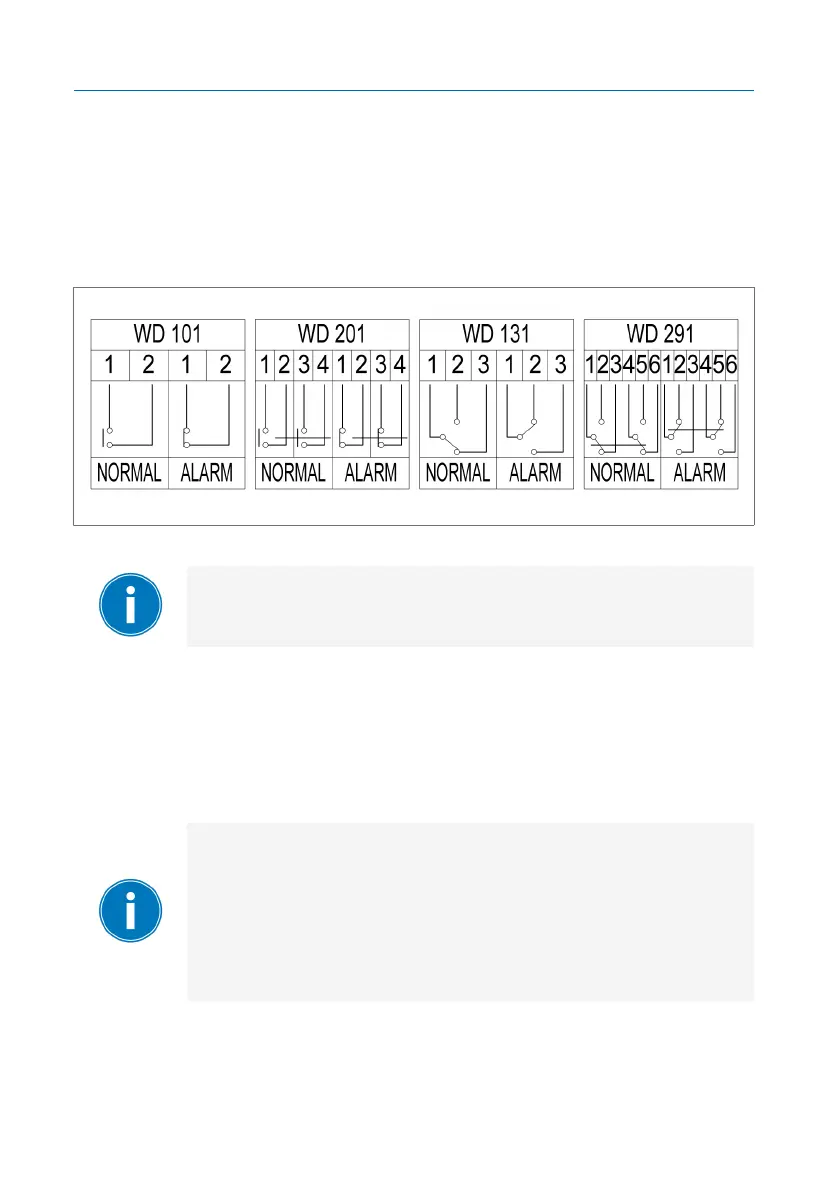
The illustration shows the normal operating conditions and the alarm states
for all available wiring connection diagrams.
Figure15: Available wiring connection diagrams
In the event of an alarm state, you can look through the in-
spection window to see if the main valve is closed.
7.2 Resetting the shutter valve
At an oil flow rate of >>30dm
3
/min, the main valve closes and the device
trips.
When the main valve closes, a pressure difference between
the two chambers in the device arises. This pressure differ-
ence leads to the main valve remaining closed and the alarm
state is triggered.
To fully equalize this pressure difference, oil must be fed from
the conservator-side chamber to the tank-side chamber via the
bypass.
 Loading...