22 v. 34 27. Oktober 2014
and commissioning
5 Installation and commissioning
5.1 Safety
Danger!
Only a qualified electrician may carry out the
installation. Before switching on for the first time,
ensure that all the cables and plugs are not damaged
and securely connected.
5.2 Connections prepared by the factory
The control unit is provided with the following connections by the
factory:
1. WX3 mains cable with a Schuko plug
2. WX12 connection assembly at the cable for connecting the
vibratory drive
3. X15 5-pole cylindrical connector for inputs of the PLC or
MRW RoboPot System
4. 4-pole cylindrical connector for X16 outputs for the
downstream control or Vib-Control 04
5. Blind plugs for connecting additional senses or outputs on the X17
terminal strip
NOTE!
The interfaces of the MRW Vib-Control 04 provide an
own 24 V potential. An amperage of 0.2 A may not be
exceeded here at interfaces in total.
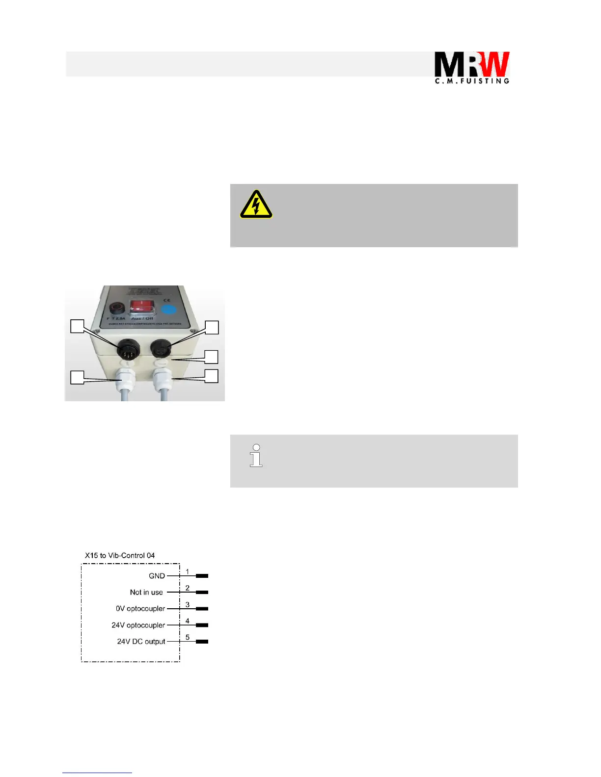
5.3 Prepared X15 connector
The X15 connector serves to start or stop a connected vibratory
drive with a PLC or with the MRW RoboPot System.
The interface provides an own 24V potential
Pin 1 = 0V, Pin 5 = 24V DC so that a mechanical switch or button
can also be connected at this point.
The input itself is an optocoupler
 Loading...