A minimum waiting period of 5 minutes must be observed after
disconnecting the control unit from the power and before opening it
so that the charge of the capacitators can decrease to a safe level.
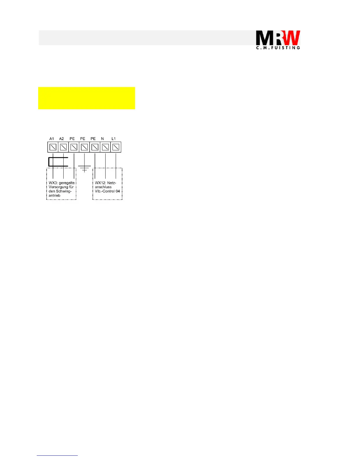
Terminals PE, N and L1 are provided for supplying power to the
Vib-Control 04. Here, 110 – 250 V at 50 or 60 Hz must be provided.
The power consumption can be 5 A in the short-term.
As a standard, a Schuko connector is connected here
Terminals A1, A2 and PE are provided for supplying power to the
connected vibratory drive.
The maximum permitted coil current of the vibratory drive is 10 A
The conductors A1 and A2 are wired through a ferrite core.
As a standard, a Schuko connector is connected here
Optionally available: 4-pole socket by Hirschmann (please also see
the Chap. “Accessories”)
 Loading...