3.2 Electrical Installation
Instructions for Electrical Connection
The device must be installed only in compliance with the applicable
regulations, otherwise the safe operation of the instrument is not
guaranteed.
-Always select appropriate cable types and wiring directly as input
power supply and output signal, the re
is 1mm
2
~2.5mm
2
or14 AWG~16 AWG.
-Must use shielded cables for measuring devices.
performance of the detector will not be guaranteed without
cables.
-Always meet the requirement of maximum cable lengths and cross-
chapter 6.2).
-
Water or impurities can penetrate the instrument through the cable. In hazardous
areas, it is recommended to install the cable in a loop just before entry into the
instrument or to slightly bend it to prevent water from entering.
The power supply is defined as 24 VDC.
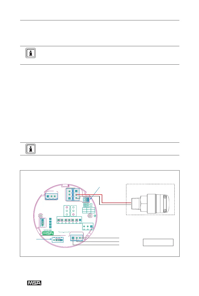
Please see the picture and table below for electrical connection
Figure 5-1 DF-8500 internal wiring (Low alarm relay configured as active mode)
-
-
4-
-
Active jumper
P2 P1
Alarm Device
P3
常闭公共端 常开
Red
NC COM NO
高报继电器 低报继电器
H-ALARM L-ALARM
故障继电器
常开 常闭
Black
FAULT RELAY NO NC
JP2 JP3
公共端 公共端
1-2 1-2
有源
COM COM
2-3 2-3
无 源
常闭
常开
P4
NC NO
5V+
Material in the dashed
TXD
P6
RXD
line rectangle is
GND
optional
Remote
P5
Sensor
Sensor
24V+
Connector
24V-
4~20mA
Controller