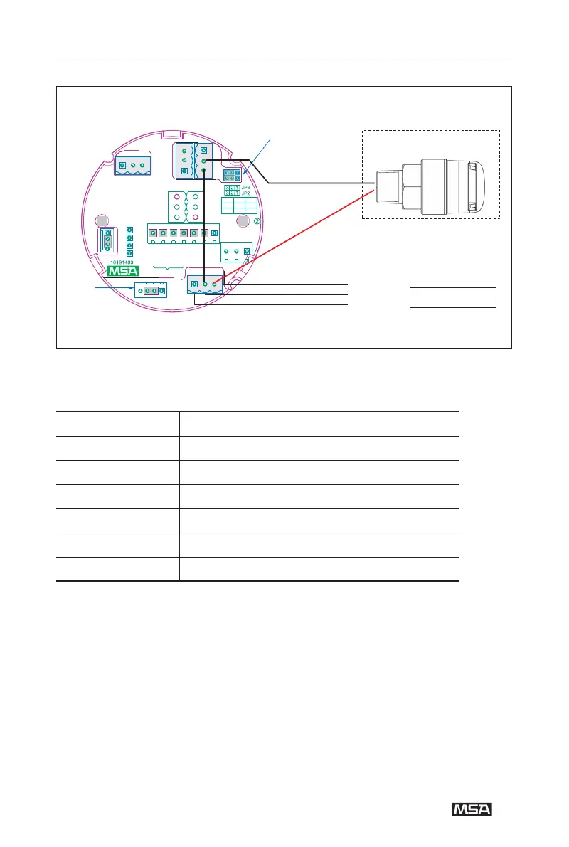
Figure 5-2 DF-8500 internal wiring (Low alarm relay configured as passive mode)
Table 1 Terminal Names and Corresponding Applications
-
-
4-
-
Terminal name Application
24V + Connect to DC 24V+
24V - Connect to DC 24V-
4-20MA (4~20) mA output of device
NO Not energized, normally open
COM Common terminal
NC Not energized, normally closed
Passive Jumper
P2 P1
P3
the black wire of
AF5000 connect to COM
常闭公共端 常开
of the low alarm relay
NC COM NO
高报继电器 低报继电器
H-ALARM L-ALARM
故障继电器
常开
常闭
FAULT RELAY NO
NC
公共端
公共端
COM
COM
常闭
常开
P4
NC
NO
5V+
Material in the dashed
TXD
P6
line rectangle is
RXD
the red wire of AF5000
GND
connect to power input “+”
optional
terminal of DF-8500
Remote
P5
Sensor
Sensor
24V+
Connector
24V-
4~20mA
Controller
Alarm Device