Figure 6 DF-8500 Power Connection Terminals
Figure 6 DF-8500 relay terminals
(Applicable to all relays)
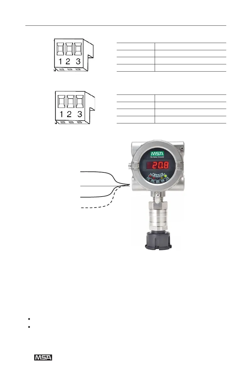
Figure 8 DF-8500 3-wire Connection
(1) Unscrew the interlocking device on the cover of the detector and the enclosure.
(2) Unscrew the aluminum cover of the enclosure.
(3) Use one hand to grab the two projections on the left and right side of the plastic
housing and pull the electronic module out of the enclosure.
(4) Insert the cable into the device.
(5) Connect the wire to the terminal.
Please use 3-wire shielded cables for power and signal lines.
Shielded cables are not required for the relay.
(6) Reinsert the properly connected electronic module into the enclosure.
(7) Reinstall the cover and fix the interlock devices.
Not energized,normally open
Not energized,normally closed