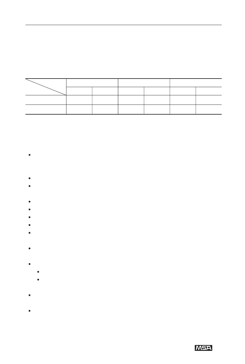
Possible structures and acquirable SILs
The following table shows which structure has to be selected to fulfill the
requirements of a specific SIL.
LDM = Low Demand Mode
HDM = High Demand or Continuous Mode
Depending on the selected configuration and the sensor version, the following
safety-relevant parameters have to be considered while implementing the safety loop:
General conditions for safe use:
The application advice and the limitations of the manual have to be considered.
calibration and maintenance, the regional and national regulations have
considered.
A defective device has to be repaired within 72 hours.
The connected controller has to monitor the 4 ~ 20 mA signal current for values
below 4mA and above 20 mA.
A functional check/calibration check has to be done for the complete system.
A visual check has to be done together with the calibration.
A system check has to be done every year.
Calibration and adjustment are part of the function/calibration check.
The test gas must be the gas to be monitored. The concentration of the test gas
has to be in the middle of the measurement range.
For zero gas, clean air free of hydrocarbon combustible gas or synthetic air has
be used.
An adjustment has to be done under the following conditions:
difference at zero > +/-5 % LEL
difference at sensitivity > +/-20 % of the rated value
If the calibration is inside of the valid tolerance, the calibration interval can be
doubled.
The maximum of the calibration interval is 52 weeks. -The gas monitor has to be
replaced if the sensor sensitivity during the operation is reduced to less than 50%
of the initial sensitivity.
SIL
level
LDM HDM LDM HDM LDM HDM
Structure 1oo1
Structure 1oo2
X
X
X
X
X
X