nections: Push the coupling of the second stage
i
ntermediate hose into the insert on the first stage
intermediate hose. Ensure the connection is secure.
INSTALLING THE FIRST STAGE REGULATOR
N
ote: The following pictures show the PR14 First Stage
Regulator. The installatin procedure for the old style first
stage regulator is identical to that for the PR14 first stage
regulator.
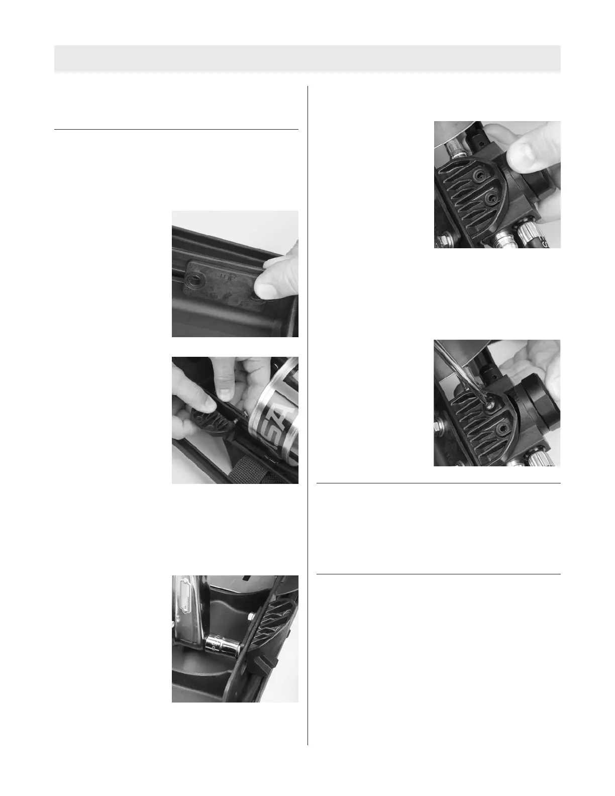
1. Install the plastic slider
onto the carrier rail.
2. Position the mounting
bracket against the
carrier rail.
Note: The cable must be captured under the mounting
bracket before it can be bolted to the carrier.
3. Apply Loctite 222 (P/N 29787) to each bolt.
4. Insert the bolts through the lock washers, flat wash-
ers, and slider into the mounting bracket.
5. Use a torque wrench
and 7/16” socket to
tighten the bolts to 35
±5 in lbs.
6. Ensure the mounting bracket slides freely.
Installing the Regulator onto the Mounting Bracket
1
. Verify that the U-clips are securely in place.
2. Position the regulator
onto the mounting
bracket.
a
. Align the regulator
mounting holes with
the mounting brack-
et holes.
3. Apply Loctite 222 (P/N 29787) to each screw.
Note: New screws have a pre-applied thread-locker and
do not require Loctite 222 application.
4. Install the screws through the mounting bracket into
regulator.
5. Tighten the screws to
35-45 in lbs.
LEAK TESTING
The upgraded air mask must be thoroughly inspected and
tested before use. Follow the “Leak Testing” section
of the User’s Maintenance Instructions (P/N 10088638).
FUNCTIONAL TEST
Before using the air mask, refer to the “visual inspection
and functional test” section of the Firehawk M7 Operation
and Instruction Manual (P/N10082858).
TAL 808 (L) Rev. 1 - 10090073
19
UPGRADE INSTRUCTIONS


 To Next Page