CONVERTING THE FACEPIECE FROM A 1/4 TURN
M
MR TO FIREHAWK REGULATOR
T
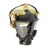
his procedure outlines the steps required to remove the
¼ Turn MMR adapter from the Ultra Elite facepiece and to
replace the spider gasket. If the facepiece being upgraded
is already configured for the Firehawk Regulator, this step
may be skipped.
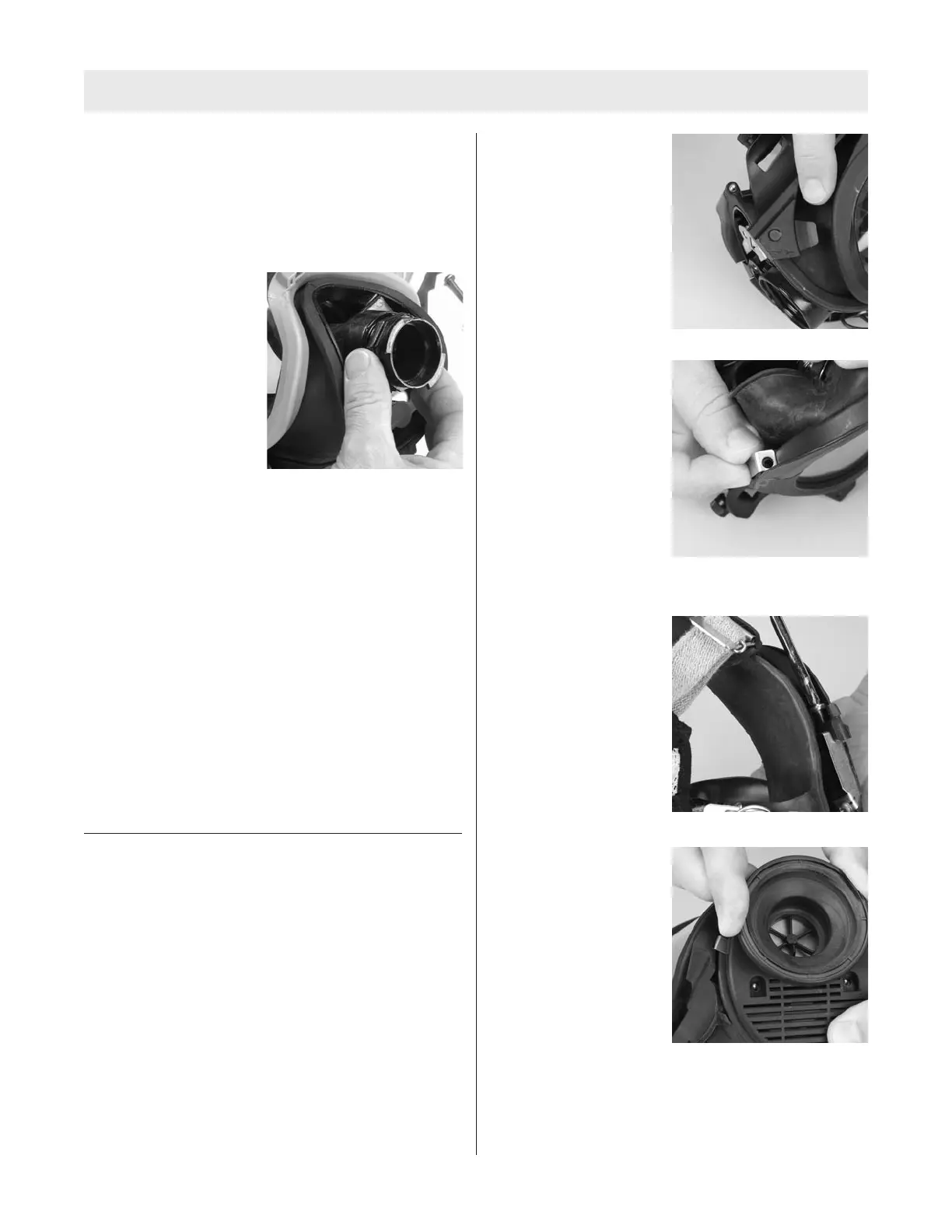
1. Unthread and remove
the old adapter assem-
bly.
2. Remove the old spider gasket from the facepiece
inlet by pulling up on the spider gasket pull-tab and
pulling the spider gasket out of the facepiece inlet.
Replacing the Spider Gasket
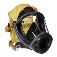
1. Install a new inlet disc on the stem of the new spider
gasket by working the hole in the center of the inlet
disc over the spider gasket stem.
2. Note that the inlet gasket has a groove around it.
3. With the pull-tab facing you, insert the spider valve
into the facepiece at an angle so that its groove cap-
tures the housing rim. The lower lip on the spider
valve must be placed under the rim in the component
housing.
Note: It may be necessary to bend the spider valve slight-
ly to work the groove under the rim all the way around.
When installed correctly, the spider valve will lay flat in the
housing and none of the spokes will be bent.
INSTALLATION OF FIREHAWK M7 HUD BRACKET
Removing the NFPA 2002 HUD Bracket
1. Remove the Nightfighter Heads-Up-Display from the
facepiece and discard.
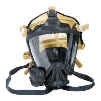
2. Remove the screw from right side of the facepiece
lens-retaining ring.
3. Remove the component housing cover. Refer to
“Removing the Component Housing” section of the
Facepiece Upgrade portion of this manual if compo-
nent housing has not yet been removed.
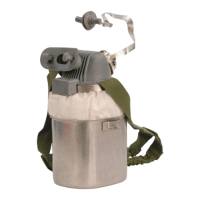
4. Remove the mounting bracket and discard.
Installation of the new Firehawk M7 HUD Mounting
Bracket to the facepiece
1. Slide the new bracket assembly onto the facepiece.
a. Make sure that
molded tab is under
the lower lens ring.
2. Align the upper tab
screw hole with the
upper lens-ring screw
hole.
3. Reinstall the screw.
a. Make sure that the
screw goes through
the hole in the upper
metal tab.
4. Align the screw hole in
the lower metal tab
with component hous-
ing screw hole.
5. Reinstall the component housing cover.
6. Check alignment and tighten screws
TAL 808 (L) Rev. 1 - 10090073
7
UPGRADE INSTRUCTIONS