11
Maintenance and Care
G1
US
2.4 Installing the Regulator Hose Assembly
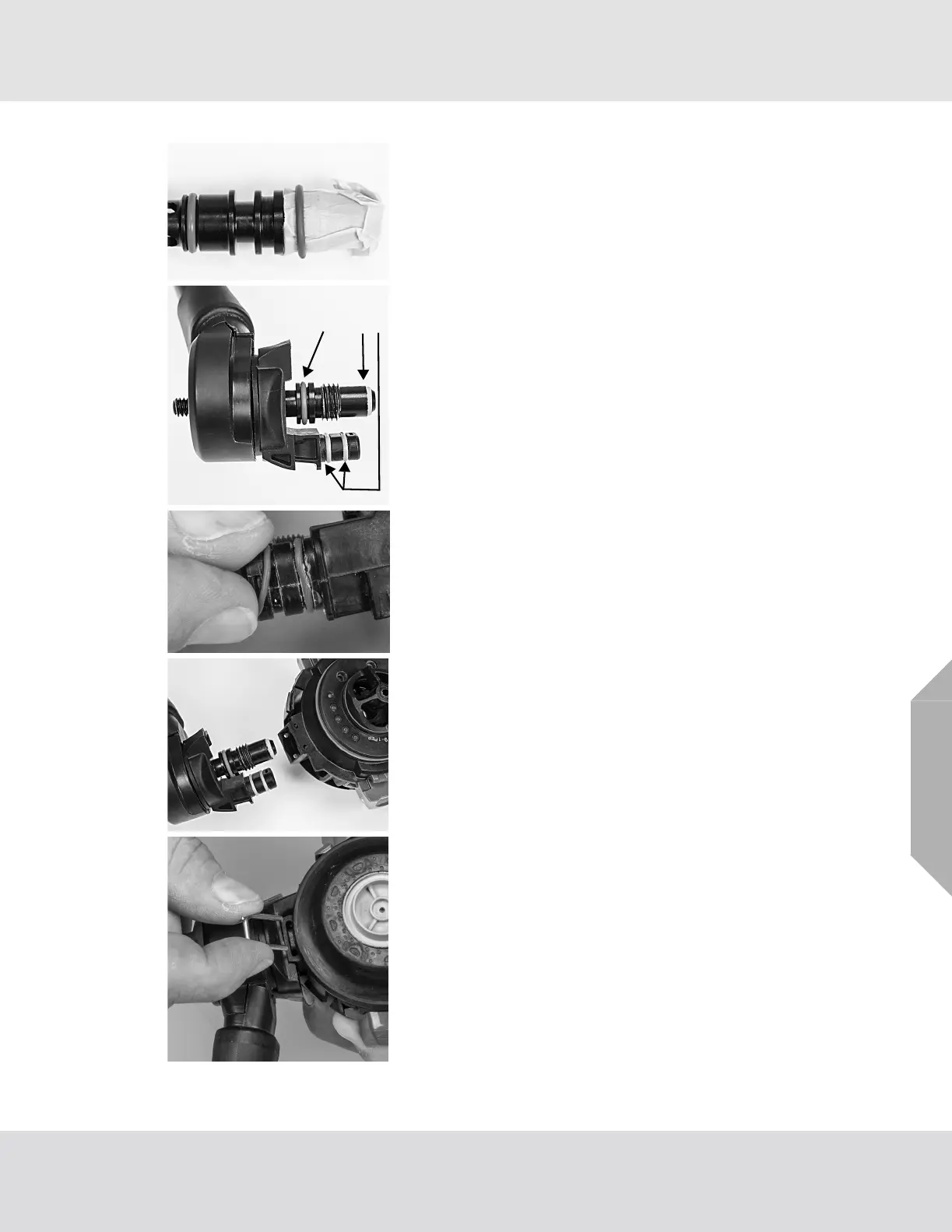
(1) Wrap protective tape or a thin piece of paper around the
bypass threads.
(2) Apply a thin film of Christo-Lube lubricant to one (1) new
size 013 orange O-ring and two (2) new 8mm green O-
rings.
(3) Install the one (1) size 013 orange O-ring on the bypass
stem, the two (2) 8mm green O-rings on the electrical
connector and one (1) new size 010 O-ring on the
bypass.
(4) Remove the protective paper or tape.
(5) Apply Christo-Lube to bypass threads.
(6) Install the bypass assembly into the bypass port.
a) Hand-tighten the bypass knob.
CAUTION! Do not over tighten the bypass knob or the seal
may be damaged.
NOTE: If the bypass does not easily screw into the valve
assembly, the valve assembly may not be properly aligned.
Ensure that the valve assembly is securely seated in the regu-
lator housing.
(7) Reinstall the U-clip into the regulator housing.
NOTE: The U-clip is held in place by the regulator cover. Use
caution to ensure that the U-clip does not slide out prior to
cover installation.
(8) Reinstall the regulator cover. (See Installing the Regu-
lator Cover for instructions.)



 To Next Page