15
Maintenance and Care
G1
US
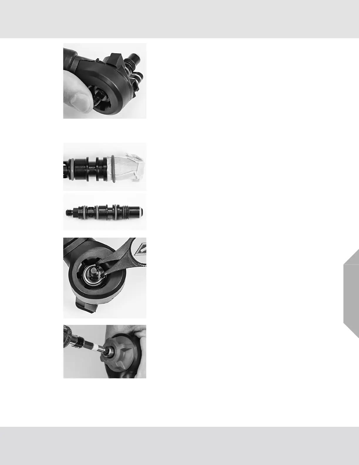
2.10 Installing the Bypass and Hose with swivel Assembly
(5) Push the bypass stem through the swivel to remove.
NOTE: Any time the bypass assembly is removed from the
regulator housing, replace the O-rings on the bypass stem and
electronic connector.
NOTE: The electronic connector cannot be removed from the
assembly. If damaged, replace the entire hose assembly.
(1) Install the new O-rings onto the grooves of the bypass.
a) Wrap protective tape or a thin piece of paper around
the threads.
b) Apply a thin film of Christo-Lube lubricant to the
one (1) new size 013 orange O-ring and the two (2)
new size 012 orange O-rings.
c) Slip the size 013 orange O-ring over the threads and
the two (2) size 012 O-rings over the other end and
install the one (1) new 010 white O-ring to the tip.
d) Remove the protective tape or paper.
(2) Insert the squared end of the bypass stem into the swivel.
(3) Using the 90° Snap Ring Pliers, reattach the C-clip to the
squared side of the bypass stem.
a) Ensure the sharp edge of the C-clip is positioned
down.
(4) Reattach the swivel cover.
(5) Apply Loctite #243 to the threads of the bypass.
(6) Reinstall the bypass knob:
a) Insert a 1/4" Drive Socket Control Blade into the
Adjustable Torque Driver.
b) Adjust the Adjustable Torque Driver to 12 +/- 1 in-lbs.
c) Fasten the center nut, applying no more torque than is
necessary to activate driver.
NOTE: Hold the bypass knob firmly while tightening the nut.
(7) Apply a thin film of Christo-Lube to two (2) new 8mm
green O-rings.



 To Next Page