17
Maintenance and Care
G1
US
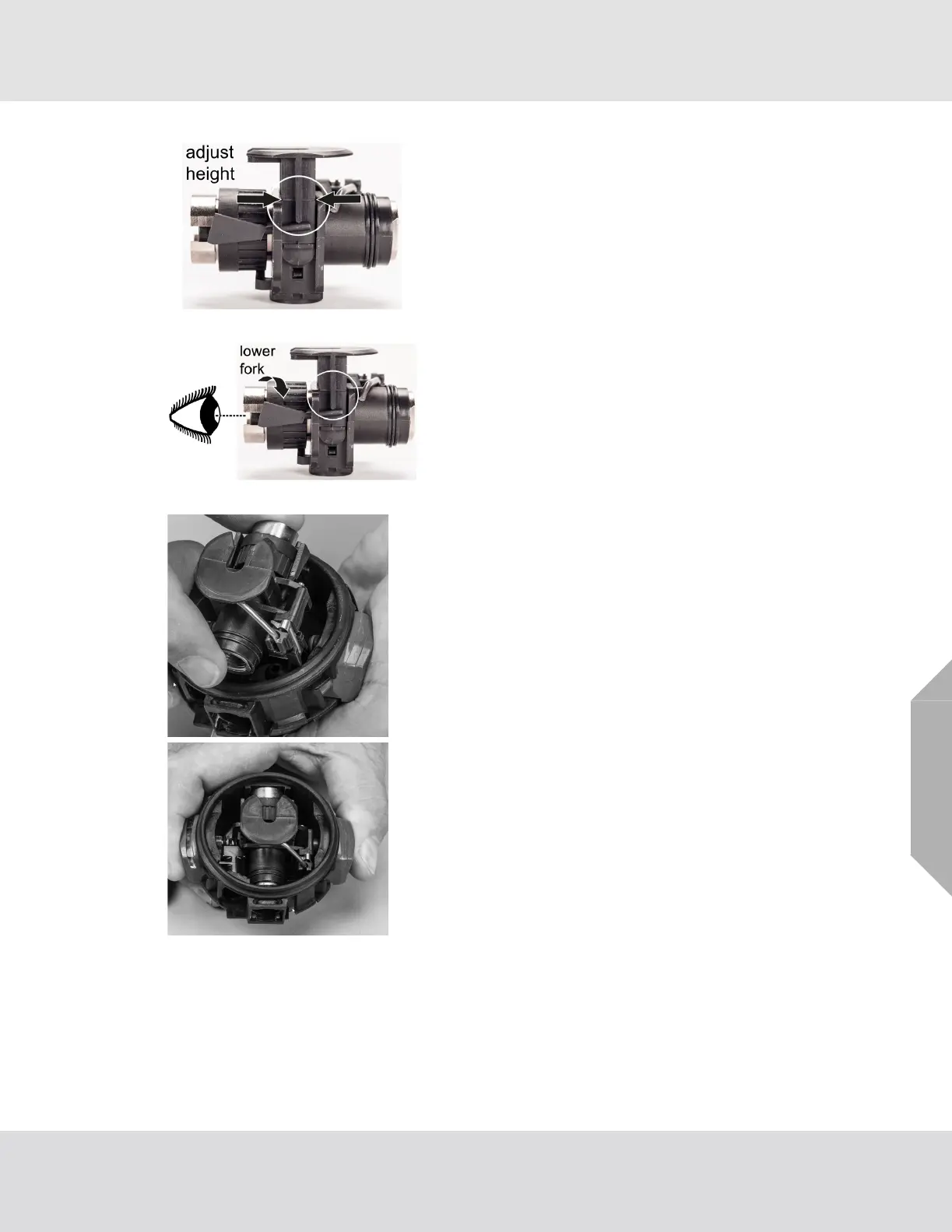
2.12 Installing the Valve Assembly
(1) Inspect and adjust valve fork height while looking at the
side of the valve housing. The valve fork assembly must
move up and down freely.
(2) Turn the adjustment wheel clockwise to lower the fork.
Turn the adjustment wheel counterclockwise to raise
the fork.
a) Press the top of the valve fork to check movement.
b) Use the height line on the side of the fork to verify that
it aligns with the top of the valve housing.
NOTE: If the height line of the valve fork is above or below the
valve housing, adjust the valve. The valve fork will not normally
require adjustment.
(3) Insert the valve assembly into the regulator housing with
the valve fork up and facing away from the bypass port.
NOTE: Ensure the valve assembly is seated securely in the
regulator housing.
(4) Push the regulator shut off buttons to ensure the valve
assembly fork is set in the raised position.
(5) Install the diaphragm. (See Installing the Diaphragm for instructions.)
(6) Install the regulator. (See Installing the Regulator Hose Assembly for instructions.)
NOTE: If the bypass does not easily screw into the valve assembly, the valve assembly may not be
properly aligned. Ensure that the valve assembly is securely seated in the regulator housing.

 Loading...