Electrical Connection
A flow detector within the Aspirated Sampling Module activates a relay
when sufficient flow exists for proper gas detection. Generally, the
Ultima X Gas Monitor output signal is routed through this relay. When
the flow is insufficient, the relay opens and the gas signal is interrupted.
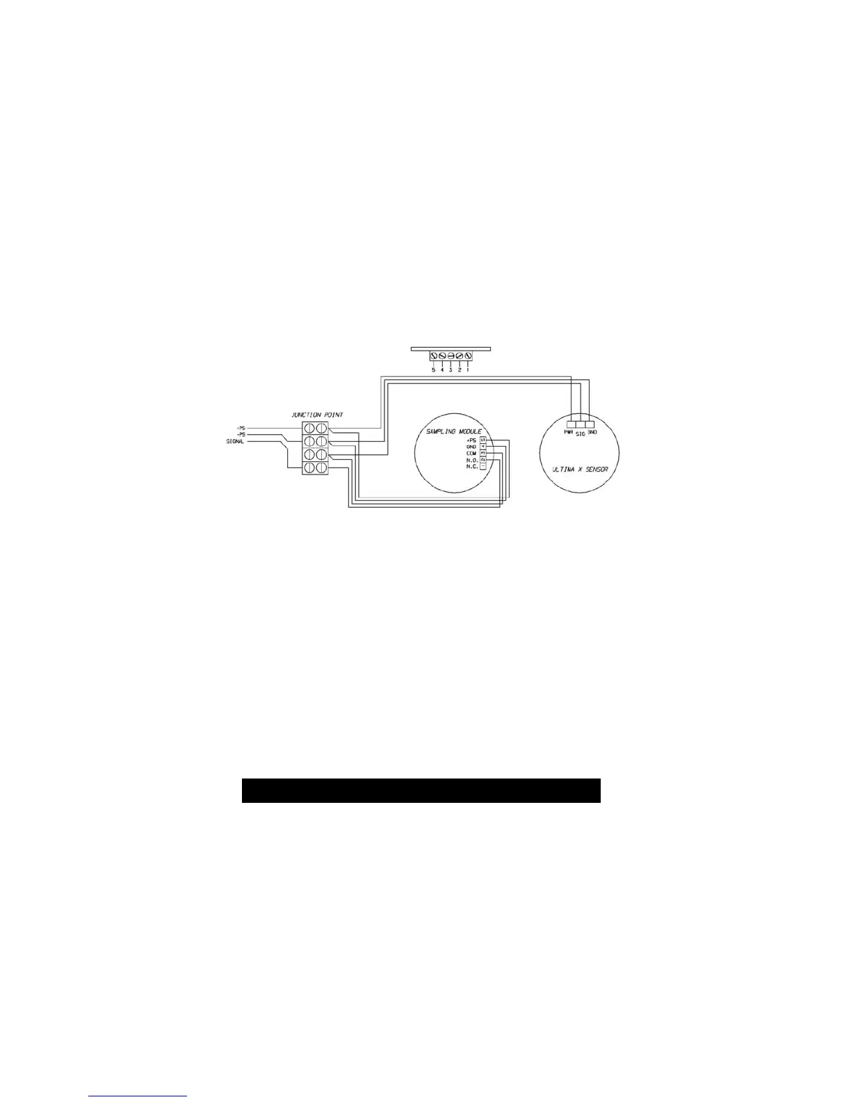
Equipment monitoring this signal can be configured to sound an alarm
when signal is interrupted. See FIGURE 2-2 for a typical wiring
schematic of the Sampling Module and Ultima X Gas Monitor.
Other devices that alert when the flow loss relay activates can be
connected to relay contact with the Aspirated Sampling Module.
NOTE: The Aspirated Sampling Module requires a four-conductor wire.
Use shielded wire if installing the system where portable two-
way radio, welding or large machinery are located. The shield of
any wire must not be grounded at the Sampling Module or the
Ultima X Gas Monitor. The shield must be grounded at one
point only, usually at the controlling instrument.
Electrical Connection Procedure
1. Turn power OFF from the receiving instrument or power supply for
the system.
Failure to remove power from instrument may damage the
Aspirated Sampling Module and/or the Ultima X Gas Monitor
during wiring.
2. If connecting the field wires to the wiring harness, observe the
identity of the conductors within the wiring harness. Connect field
wires to the appropriate harness conductors.
"
CAUTION
Figure 2-2. Typical Wiring
2-8
 Loading...


