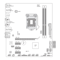
Fan Power Connectors: CPUFAN,SYSFAN1~2
The fan power connectors support system coolng fan wth +12V. When connectng the
wre to the connectors, always note that the red wre s the postve and should be con-
nected to the +12V; the black wre s Ground and should be connected to GND. If the
manboard has a System Hardware Montor chpset on-board, you must use a specally
desgned fan wth speed sensor to take advantage of the CPU fan control.
CPUFAN SYSFAN1~2
Important
Please refer to the recommended CPU fans at processor’s ocal webste or consult
the vendors for proper CPU coolng fan.
CPUFAN support Smart fan control. You can nstall
Control Center utlty that wll
automatcally control the CPUFAN speeds accordng to the actual CPUFAN tem-
peratures.
Fan cooler set wth 3 or 4 pns power connector are both avalable for CPUFAN.
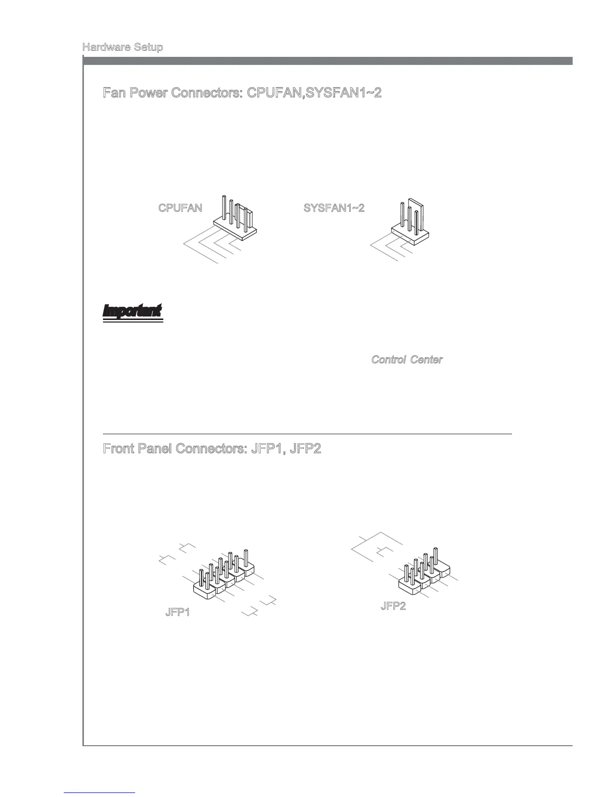
Front Panel Connectors: JFP1, JFP2
These connectors are for electrcal connecton to the front panel swtches and LEDs.
The JFP1 s complant wth Intel
®
Front Panel I/O Connectvty Desgn Gude.