TECHNICAL MANUAL
Chapter 7 - Installation
NGSi 05÷15
11
ENGLISH
EN
The data in this manual are not binding and they can be modified by the manufacturer without notice. Reproduction of this manual is strictly prohibited
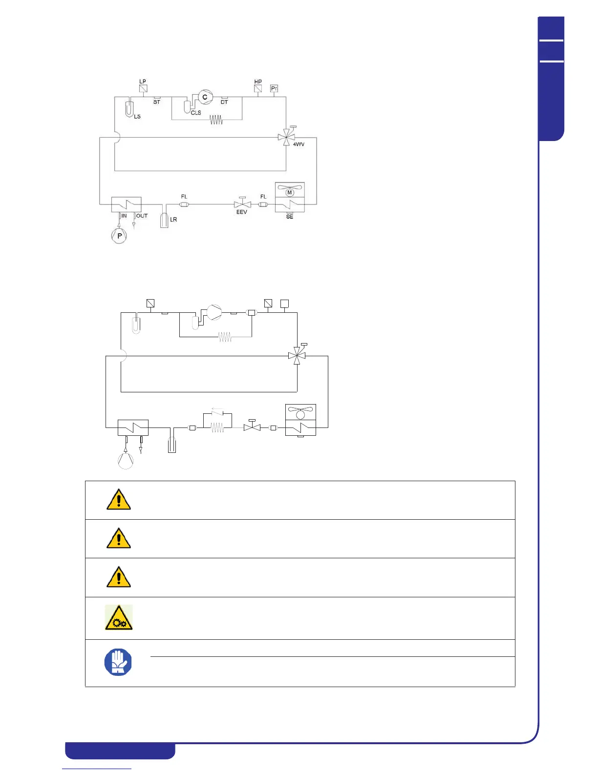
7.5 5-9 kW chiller diagram
7.6 12-15 kW chiller diagram
C Compressor
CLS Compressor liquid separator
ST Compressor intake temperature
DT Compressor outlet temperature
HP High pressure transducer
Pr High pressure switch
LP Low pressure transducer
LS Liquid separator (on 07, 10 and 15 models only)
4WV Cycle reverser valve
LR Liquid receiver
EEV Electronic expansion valve
FL Filter
M Axial fan
SE External air temperature
P Circulator installed on unit
IN Water intake temperature
OUT Water outlet temperature
C Compressor
CLS Compressor liquid separator
OS Oil separator (on 10 and 15 models only)
ST Compressor intake temperature
DT Compressor outlet temperature
HP High pressure transducer
Pr High pressure switch
LP Low pressure transducer
LS Liquid separator (on 07, 10 and 15 models only)
4WV Cycle reverser valve
LR Liquid receiver
EEV Electronic expansion valve
NRV Check valve (may be fitted on some models)
FL Filter
M Axial fan
SE External air temperature
P Circulator installed on unit
IN Water intake temperature
OUT Water outlet temperature
CP Capillary
WARNING:
The unit must be installed in a manner which allows maintenance and repairs. The warranty does not cover costs of the
platforms or handling equipment required for any work on the unit.
All maintenance and inspection procedures must only be performed by QUALIFIED STAFF.
Before doing any work on the unit, make sure that the electricity supply is disconnected.
WARNING:
The unit contains several moving components. Take great care when working in their vicinity, even if the electricity supply is
disconnected.
The compressor heads and delivery pipeline are often at quite high temperatures. Take special care when working in the
vicinity of the heat exchanger coils.
The aluminium fans are particularly sharp and may cause serious injuries.
SE
EEV
LR
IN
OUT
4W V
DT
LP
HP
ST
M
P
C
LS
OS
FL FL
NRV
CP
CLS
Pr